Knowledge / Maintenance and reliability
Thickness measurements and remaining life: corrosion rates with uncertainty
Interpret repeated thickness readings with measurement uncertainty, location matching, local pitting and the correct minimum-thickness criterion.
On this page
Remaining life calculated from thickness is a conditional projection, not a certificate that a structure or pipe will remain acceptable until a predicted date. It depends on what was measured, whether the same material location was revisited, how corrosion may change and which acceptance criterion applies. A useful assessment separates measurement, deterioration model and engineering acceptance before combining them.
Understand what an ultrasonic reading represents
In a simplified normal-incidence pulse-echo model, thickness is d = cΔt/2, where c is material sound speed and Δt is the round-trip travel time. For assumed c = 5,900 m/s and Δt = 3.2 microseconds, d = 9.44 mm. If the same echo is interpreted using 6,000 m/s, the reading becomes 9.60 mm. The 0.16 mm difference comes from the velocity assumption, not metal growth.
Real probes and instruments require suitable calibration, zero correction and interpretation of the echo. Surface roughness, couplant, curvature, temperature and material condition affect the measurement. Evident’s corrosion-gauging guidance discusses these practical limitations, including temperature effects on velocity and probe response. A plausible digital number is not sufficient evidence that the intended back-wall echo was measured.
Separate coating from the load-carrying metal
Paint or another coating can affect travel time and echo selection. A suitable validated technique may separate coating and metal thickness, but this capability depends on the instrument, transducer, coating and signal quality. Evident’s coating tutorial describes several approaches and their limitations. Do not assume every thickness gauge automatically removes coating contribution.
Keep the surface preparation and measurement mode in the record. Changing from a coated surface to a cleaned surface or from one echo mode to another can create an apparent trend step. If a historical reading’s method is unknown, its comparability may be limited. A decision near the acceptance boundary should not rely on a silent assumption that all previous readings measured exactly the same physical thickness.
Return to identifiable locations
A thickness history requires repeatable positions: structural member, side, distance from a reference, grid point and relevant orientation. Measuring a nearby thicker patch on the next survey can conceal local loss. Location uncertainty is especially important around pits, welds, stiffener connections and areas of disturbed flow. Photographs and mapped coordinates make later comparisons more defensible.
Distinguish a point reading, an area average and the minimum found in a scan. They answer different questions. More measurements can improve coverage but do not guarantee that a narrow pit was intercepted. A sparse grid across a large surface may support broad uniform-loss characterization while leaving local-defect detection incomplete. The inspection plan should follow the expected morphology and consequence, not just a target number of readings.
Calculate a rate on a defined time basis
An original example revisits the same representative region at 9.6 mm and, three years later, 9.0 mm. The average loss rate is (9.6 − 9.0)/3 = 0.20 mm/year. This is a net historical rate over that interval. It does not establish that loss was linear every month or that the future rate will remain constant.
Using an explicitly assumed minimum acceptable thickness of 7.8 mm, a uniform-loss projection gives (9.0 − 7.8)/0.20 = 6 years. The 7.8 mm value is invented for the example, not a rule for any hull or pipe. The projection assumes unchanged mechanism, environment, loading basis and acceptance criterion. It is time to a modelled thickness boundary, not a permitted next-survey interval or permission to continue operation.
Show the effect of measurement bounds
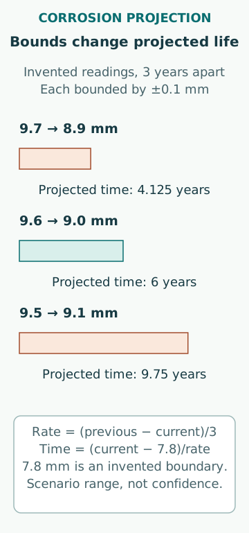
Now assume each example reading could differ by ±0.1 mm from its reported value, treated as simple bounds rather than statistical standard uncertainties. The largest consistent loss is from 9.7 to 8.9 mm, giving 0.2667 mm/year. Using the same lower current thickness and the unrounded loss rate, the projected time is (8.9 − 7.8)/[(9.7 − 8.9)/3] = 4.125 years. The opposite paired limits give 9.75 years.
The resulting 4.1–9.8 year span is a scenario range, not a confidence interval. Errors may be correlated when the same calibration or velocity assumption is reused; location and morphology can dominate instrument error. More digits in the rate do not reduce that uncertainty. If the measured change is comparable with measurement uncertainty, a precise rate claim is weak and better evidence may be required.
Do not average away local pitting or another mechanism
Uniform thinning and localized pitting impose different assessment questions. A region with a reassuring average can contain a deep narrow pit or groove. Cracking, deformation and connection damage can also govern fitness even when wall thickness is adequate. A general corrosion-rate projection cannot establish resistance to all these mechanisms.
Assess local morphology, minimum readings, extent and location using the applicable engineering criteria. Avoid importing a percentage wastage limit from another member, ship type or rule edition. Thickness acceptance can depend on structural role, original design, local and global strength and specific corrosion pattern. A pipe’s pressure-retention requirement is not interchangeable with a hull plate’s structural criterion.
Check why the future could differ from the past
Coating breakdown, changing cargo or ballast exposure, altered temperature, deposits, flow and repairs can change corrosion behaviour. A long historical average can understate a recent acceleration. Compare shorter and longer intervals where data support it, but do not fit a trend through incomparable locations merely to obtain more points.
A coating repair may reduce future attack, yet the previous lost metal does not return. An apparent rate improvement after changing measurement method may not be physical. Record environmental and maintenance changes beside the thickness history. Where conditions change materially, the old extrapolation becomes a scenario to reassess rather than a forecast to retain by default.
Investigate places where a valid reading is unavailable
Failure to obtain a stable back-wall echo is not evidence of adequate thickness. Severe roughness, geometry, poor coupling, a defect or thickness outside the validated range can all prevent a usable reading. Record the location as unmeasured or unresolved and investigate with an appropriate alternative through the inspection plan. Substituting the neighbouring reading creates information that was never observed.
The same caution applies when an instrument repeatedly displays an unexpectedly high value in a badly deteriorated area. Check the waveform, calibration, mode and probe applicability before accepting it. A measurement programme should report coverage gaps and the response to them, not only a spreadsheet of successful numbers. A map that omits difficult locations can make the most damaged area disappear from the apparent condition assessment.
Connect the calculation to competent acceptance
DNV’s UTM page explains its service-supplier approval context for measurements used in class decisions. The current applicable class procedure, survey scope and acceptance basis must be established for the particular vessel. A general educational calculation does not replace that process or a competent assessment of the actual structure.
A useful report includes locations, method, calibration evidence, surface condition, raw readings, uncertainty, morphology, assumed rate and the source of the minimum-thickness criterion. State what the projection excludes and what would trigger reassessment. The result is a transparent account of present evidence and conditional future loss, with inspection and repair decisions made through the applicable engineering and survey arrangements.
Sources
- Corrosion Thickness Gauging with Dual Element Transducers · Evident · Source check date: 2026-10-06
- Precision Ultrasonic Gauging for Measuring Coatings · Evident · Source check date: 2026-10-06
- Ultrasonic Thickness Measurements · DNV · Source check date: 2026-10-06