Knowledge / Maintenance and reliability
Elastomer-seal ageing: swelling, compression set and fluid compatibility
Separate fluid-induced volume change from lost elastic recovery, calculate compression set correctly, and use compound-specific evidence rather than a colour or generic rubber name.
On this page
An elastomer seal works through geometry, deformation and material response. Ageing can change all three. A seal may become larger but less mechanically capable, or remain close to its original dimensions while losing recovery. The practical question is not simply whether the removed ring looks intact. It is whether the actual compound can keep the required sealing contact through the fluid, temperature, pressure and motion history of the application.
The compound identity matters more than its appearance
An elastomer family name narrows the chemistry, but does not fully specify a seal compound. Formulation, cure, fillers and other ingredients influence its mechanical and environmental response. Colour and nominal hardness alone do not uniquely identify the material. A replacement should therefore retain the approved compound identity and dimensions, not merely resemble the removed part.
The relevant exposure includes the process fluid, lubricant, cleaning agent and any temporary flushing medium. Mixtures and their concentration can differ from a chart’s single named chemical. List the sequence of exposures as well as the normal steady condition; a short cleaning stage may challenge a material selected only for the operating oil.
Swelling, extraction and chemical damage are different paths
Trelleborg distinguishes absorption, extraction of ingredients and chemical degradation. Absorption can increase volume; extraction can leave the compound smaller or alter its properties. Chemical reactions can change the polymer network. More than one mechanism can operate at the same time, so a small net dimensional change does not establish that no material change occurred.
A free immersion coupon and a compressed seal in a groove do not have identical boundary conditions. The exposed surface, diffusion distance and mechanical constraint differ. A measured volume change should retain its specimen geometry, fluid composition, temperature, exposure duration and post-exposure handling. Otherwise, comparing two percentages can compare different experiments rather than different materials.
Compression set measures unrecovered deformation
Parker’s Figure 2-9 defines compression set relative to the original imposed deflection. Let h0 be the original specimen height, hs the compressed spacer height, and hr the recovered height after the stated test and recovery conditions. The deflection-based result is CS = (h0 − hr)/(h0 − hs) × 100%. The denominator is imposed deformation, not the original height.
ASTM D395-18(2025) distinguishes constant-force and constant-deflection methods; its public description places compression-set tests mainly in the context of static stressing. Method, temperature, duration, medium and recovery procedure belong with the reported result. A number without that basis cannot rank compounds reliably for a different operating duty.
Worked recovery example: 40% is not 40% thickness loss
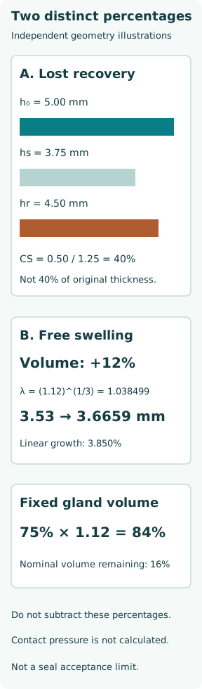
For an original illustration, set h0 = 5.00 mm, hs = 3.75 mm and hr = 4.50 mm after a stipulated recovery procedure. The imposed deformation was 1.25 mm, or 25% of initial height. The unrecovered height is 0.50 mm, giving CS = 0.50/1.25 × 100 = 40%. The thickness loss is only 10% of the initial 5.00 mm; these two percentages have different denominators.
This geometric calculation does not specify a compliant laboratory procedure or an acceptable service limit. A 40% result is not a statement that 40% of sealing force has been lost. Force recovery and stress relaxation require mechanical information or measurement; they are not obtained by multiplying the original force by one minus compression set.
A separate clearance comparison shows the recovery consequence
For a purely geometric comparison, place the original 5.00 mm specimen across a hypothetical 4.00 mm gap: interference is 1.00 mm, or 20% of its original height. Use the recovered 4.50 mm height in the same gap and interference is 0.50 mm, or 11.11% of that recovered height. This shows how dimensional recovery affects available interference when a joint changes position or is reassembled.
The comparison does not authorize reusing the aged seal or predict contact pressure. Real O-ring cross-sections deform into a constrained groove, and pressure energization, friction, hardness changes and surface condition matter. A joint that remains sealed at one steady pressure may respond differently after cooling, pressure removal or motion. Dimensional clearance alone cannot establish that response.
Volume swell is not the same percentage of diameter growth
In an independent free-swelling illustration, suppose the volume increases by 12% and the unconstrained expansion is uniform in all three directions. The linear scale factor is λ = (1.12)^(1/3) = 1.038499. Linear dimensions rise by about 3.850%, not 12%. An initially free circular cross-section of 3.53 mm would become 3.6659 mm under this ideal isotropic assumption.
This is a geometric conversion, not a material prediction. A stretched or confined ring need not preserve a circular section or expand isotropically. Its swelling response may also differ from the free specimen’s result. Do not apply the free diameter directly as an installed interference without checking the actual groove, constraint and material behaviour.
A volume-fill screen identifies another geometric limit
As a separate bookkeeping screen, suppose initial seal volume occupies 75% of a fixed gland volume. If its volume actually increases by the stipulated 12% inside that gland, the fill fraction becomes 0.75 × 1.12 = 0.84, or 84%. The remaining nominal volume is 16%. This uses total volumes; it does not assume the cross-section shape derived for the free specimen survives installation.
The example does not establish that 84% fill is acceptable. Groove tolerances, thermal expansion of both materials, stretch, assembly squeeze and pressure-driven movement must be considered. Nor should the 12% swell be subtracted from the 40% compression set: one is relative to volume, the other to imposed deformation, and they describe different experiments. A coupled test or validated model is needed to combine their effects.
Time and local temperature belong in compatibility evidence
A useful qualification sequence compares initial properties with properties after a defined exposure and, where relevant, after recovery or drying. Keep volume, hardness, strength or elongation and compression response separate in the record. The chosen endpoints should match the failure mode being assessed. A short immersion result cannot on its own establish a long operating life or the response to repeated switching between fluids.
Trelleborg also notes that compatibility depends on temperature and time, and that friction can raise a dynamic seal’s interface temperature above bulk-fluid temperature. Qualification should therefore use the relevant exposure at the seal. A generic maximum temperature for a material family is insufficient without the fluid and mechanical duty to which that value applies.
Use failure evidence to test a cause, not assign one by sight
Trelleborg’s failure guide lists different possible contributors to flat sections, cracks, swelling and damaged edges. Photograph and identify the removed seal, preserve its location and orientation, and compare dimensions only with a traceable reference and known handling state. Installation cuts, extrusion and chemical ageing can coexist. The appearance should guide a hypothesis and further checks, not replace them.
A useful replacement decision connects the exact compound and fluid sequence with geometry, pressure, motion, temperature and evidence from appropriate exposure tests. The calculations above help keep recovery, linear growth and volume fill distinct. They provide a way to audit the assumptions in a seal assessment while leaving the actual material acceptance and joint limits with the equipment’s qualified design.