Knowledge / Maintenance and reliability
Flexible-hose damage: bend radius, twist and pressure cycling
Read hose routing as a combined geometry and fatigue problem, distinguish inside radius from centreline radius, and count duty cycles without turning a laboratory impulse claim into a service-life prediction.
On this page
A flexible hose is a pressure-containing composite assembly, not simply a soft pipe that can be placed anywhere. Its inner tube, reinforcement, outer cover and end fittings work together. A route can look tidy at rest yet impose a tight bend, torsion or concentrated motion when pressure rises or a connected component moves. The useful assessment follows the entire motion envelope and the actual hose-and-fitting combination.
The cover is only one part of the pressure boundary
The inner tube must suit the fluid, while the reinforcement carries the main pressure-related loading and the cover protects against the environment. The end connection transfers load through a specified assembly design. Damage or incorrect assembly can affect the reinforcement or fitting interface without producing an obvious external leak at the moment of inspection.
Visual inspection therefore identifies important rejection evidence but cannot quantify remaining pressure capacity. An intact-looking cover is not a pressure test certificate or a remaining-life measurement. Record the hose type, size, manufacturer-approved fitting combination, assembly identity and service history so that the physical object can be checked against a traceable specification.
A minimum bend radius has a measurement convention
Parker requires the listed minimum bend radius to be respected and draws attention to the hose-to-fitting junction. The product’s definition matters: an inside radius and a centreline radius are not interchangeable. Confirm the catalogue convention for the actual hose, including any distinction between a static route and repeated flexing.
Bending too tightly changes the geometry of the tube and reinforcement and can concentrate deformation. A simple homogeneous-beam strain formula cannot establish the allowable bend of a braided or spiral composite hose. Its reinforcement angle, layers, material interaction and ovalization make product qualification necessary. The worked geometry below checks space, not fatigue strength.
Worked loop: convert radius before calculating length
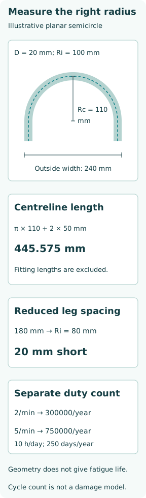
Use a hypothetical hose with 20 mm outside diameter and a stipulated minimum inside bend radius of 100 mm. These are illustrative inputs, not a catalogue recommendation. For a planar semicircular loop, the centreline radius is 100 + 20/2 = 110 mm. The curved centreline length is π × 110 = 345.575 mm.
If the ideal flexible segment includes two straight tangent portions of 50 mm each, its centreline length is 445.575 mm. The parallel leg centre spacing is 2 × 110 = 220 mm, and the loop’s outside width is 220 + 20 = 240 mm. Fitting insertion, rigid end lengths, assembly-length definitions and tolerances are excluded. Consequently, 445.575 mm is not a hose cutting instruction.
A shorter envelope cannot be fixed by forcing the bend
If the same ideal semicircle is forced into a leg centre spacing of 180 mm, its centreline radius becomes 90 mm and its inside radius 80 mm. It misses the stipulated 100 mm requirement by 20 mm. Making the hose longer somewhere else does not automatically repair this local curvature. The route or connection arrangement must change so the required envelope is available.
The 50 mm straight tangent portions above are also example inputs, not universal minimum distances from a ferrule. The specified end geometry governs where flexing may begin. Evaluate the route at both travel limits and during intermediate motion, with allowances for nearby equipment and tolerances; a drawing of one parked position cannot establish all those conditions.
Twist is different from bending in a plane
A hose can bend without being twisted about its own axis. Conversely, incorrect fitting orientation can introduce torsion even when the visible bend is gentle. As a descriptive calculation, 15° of end rotation over a 0.40 m flexible length corresponds to an average 37.5°/m. This is not an allowable twist rate, reinforcement strain or failure criterion.
Gates illustrates routing that accommodates component motion without twisting and allows pressure-related length change. An end that swivels for assembly is not automatically a live swivel rated for continuous rotation. The proper connection and route must prevent unintended torque reaching the hose over the complete motion, rather than relying on the apparent flexibility of the cover.
Pressure can change both length and loading
In a separate example, stipulate a 2% shortening of a 400 mm unpressurized flexible segment at its working condition. The change is −8 mm and its resulting length 392 mm. This is an assumed response for illustrating routing allowance; actual change, including its sign, comes from the specified product. A taut installation can transfer the resulting constraint into fittings or a local bend.
Supports and clamps should control unwanted movement and abrasion while allowing the intended deformation. Clamping a bend or linking parts with different movement can create a new concentration of strain. Neither maximum slack nor maximum restraint is a universal solution. The geometry has to accommodate the actual pressure, temperature and mechanical-motion combination.
Count the exposure, then retain what a count leaves out
For an original duty-count example, define one cycle as one repeated low-to-high-to-low pressure excursion. At 2 cycles/min, 10 h/day and 250 days/year, exposure is 1200 cycles/day and 300000 cycles/year. Under the same time schedule, 5 cycles/min gives 750000 cycles/year, a factor of 2.5 more excursions.
The count does not assign equal fatigue damage to different excursions. Pressure range, mean level, rise time, temperature, flexing and dwell differ between duties. Avoid converting a manufacturer’s laboratory cycle count directly into operating years. Danfoss, for example, states its EC600 impulse test in association with specified 1W fittings. That association is part of the evidence, not an interchangeable detail.
A steady gauge and a burst rating do not define the duty
Parker distinguishes transient pressure peaks from an ordinary gauge indication and working pressure from burst-test pressure. A slow display may miss a short peak. Use an appropriate measurement basis when pressure surges are suspected, and compare the assembly’s permitted working conditions with the actual extremes, including temperature and fluid compatibility.
A proof or functional test has a defined pressure, medium, duration and acceptance procedure. Passing it does not reconstruct the earlier fatigue history or certify indefinite future flexing. The lowest applicable component rating and the qualified assembly process matter together; combining individually familiar hose and fittings does not by itself qualify a new assembly.
Inspection should connect defects to the route and history
Observe the isolated, depressurized assembly for routing, fitting position, cover damage, flattening, abrasion and changes from its documented state. Include hidden contact points and the area near the ferrules. Suspected pressurized leaks require the equipment’s safe isolation method; feeling along a live hose is not an inspection technique. Replacement criteria and intervals come from the approved maintenance basis.
A useful record connects the defect with movement, pressure history, temperature, fluid, assembly identity and nearby contact surfaces. Replacing a damaged hose with the same route can reproduce the original cause. The goal is a qualified assembly operating within its geometric and environmental envelope, supported by inspection and exposure records rather than by appearance or a single impressive pressure number.