Knowledge / Rules and safety management
Energy isolation: stored energy and verification of a safe state
Distinguish stopping equipment from isolating hazardous energy, account for electrical, pressure and mechanical storage, and define what verification must establish.
On this page
A machine can be stopped while still capable of releasing hazardous energy. Electrical storage, pressure, elevated mass, spring force and thermal energy may remain after normal operation ends. Another source can also re-energize the system through a connection or automatic function. Energy isolation is therefore a system-boundary problem as well as a work-control problem. The relevant question is whether hazardous energy can reach the people and parts involved in the task, not whether the normal control display says off.
Distinguish a stop command from isolation
The US shipyard definitions in 29 CFR 1915.80 distinguish energy-isolating devices from control-circuit devices such as push buttons. The distinction expresses an important physical point: a command to stop depends on the control path and does not necessarily interrupt every energy source. The legal provision has its own US shipyard applicability.
A remote command, interlock or emergency-stop function can have a valuable operational role while serving a different purpose from the isolation required for servicing. A failed contact, alternate feed or unexpected command can matter to the work boundary. The actual equipment and approved work arrangement determine what constitutes effective isolation; this article does not supply a switching or valve sequence.
Identify the energy domains and their paths
OSHA’s shipyard hazardous-energy rule addresses identification, isolation and verification before relevant servicing. A generic shipboard assessment should identify electrical, hydraulic, pneumatic, mechanical, gravitational, thermal and process-material sources that can affect the task. The list is not complete merely because the main electrical supply has been named.
Follow connections across the chosen boundary. An electrically driven pump may also be connected to pressurized liquid and a common header. An actuator may have a spring return or accumulator. An elevated mechanism may move under gravity. The work may expose a different part of the system than the operator normally observes, so the energy path must be traced to that part.
Recognize electrical energy remaining after disconnection
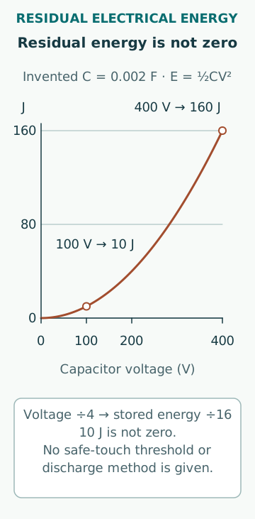
The capacitor-energy relation in OpenStax’s physics text is E = ½CV². In an invented example, a 0.002 F capacitor at 400 V stores 160 J. If its voltage later measures 100 V, the ideal stored energy is still 10 J. The energy has decreased by a factor of sixteen; it has not become zero.
These values are arithmetic examples, not safe-touch thresholds or a discharge method. Actual circuits can contain multiple capacitors, batteries, alternate feeds and paths for recharging. A status lamp can also fail independently of the energy it appears to indicate. Verification must address the relevant circuit and equipment conditions through the authorized method, rather than infer absence of hazard from elapsed time or a dark display.
Treat pressure as a force source, not just a gauge number
For an illustrative pressure difference of 2.0 MPa acting on an effective area of 0.0050 m², the corresponding force is 10,000 N, or 10 kN. This calculation uses differential pressure at the moving boundary. It does not calculate the total stored energy, which depends on volume, compressibility, geometry and the release process.
A zero reading on one gauge does not necessarily characterize a trapped region behind a closed path or an obstructed sensing connection. Pressure can also reaccumulate through leakage, thermal expansion or another connected source. The assessment must identify the relevant volumes and potential re-energization, with verification appropriate to the equipment rather than a general assumption that a stopped pump means no pressure.
Include gravity and elastic storage
An invented 200 kg mass elevated 1.5 m above a lower reference has gravitational potential energy mgh = 200 × 9.81 × 1.5 = 2,943 J. Removing motor power does not remove that potential energy. Whether the mass can move into the work area depends on the mechanical arrangement and the means that restrain it.
An ideal linear spring with stiffness 20,000 N/m compressed by 0.10 m stores ½kx² = 100 J and exerts 2,000 N at that compression. Real mechanisms can include preload, nonlinear springs, friction and changing leverage. The example shows why stored mechanical energy needs its own assessment. It is not a design for a restraint or a procedure for releasing the spring.
Define what the verification is meant to prove
HSE HSG253 treats isolation as a planned and verified arrangement with attention to stored energy and reinstatement. A verification method should relate to the hazard and the actual work boundary. Testing a control response, checking a valve-position indication and measuring an energy quantity can provide different evidence; none should be assumed to prove every source has been controlled.
The measurement or test must itself be suitable for the range, location and conditions involved. Its result should be interpreted against the defined safe state, including any retained energy that is securely controlled rather than physically absent. Zero energy is useful shorthand only when the relevant hazardous-energy conditions are clear. It is not a substitute for an explicit description of what remains and how exposure is prevented.
Maintain the state while the work continues
An isolation verified at the start can be undermined by another operation, changed connection, loss of a restraint or reaccumulation of energy. The work-control arrangement must preserve the intended boundary over the task’s duration. Where several workers or teams are involved, their protection must not depend on an undocumented assumption that someone else will remember who is still exposed.
A shift handover or temporary interruption needs to carry the actual status and outstanding work. A lock or tag has meaning within the system that identifies the device, source, protected task and authorized roles. The number of tags is not a measure of isolation quality if the underlying boundary is wrong. The protective state should remain understandable to those who rely on it.
Treat restoration as another controlled change
Returning equipment to service changes the energy state and can affect people beyond the immediate work area. The restoration assessment needs to account for completed work, removed temporary arrangements, reassembled boundaries, retained tools or materials and the readiness of affected personnel and systems. A closed maintenance task alone does not establish all those conditions.
Testing after maintenance may require a different controlled state from either full isolation or ordinary operation. That state needs its own defined limits and responsibilities. The objective is not to improvise a universal sequence, but to recognize that verification of repair and restoration of energy are distinct parts of the actual authorized procedure.
Keep the physical argument visible
A useful isolation record connects the task boundary to every relevant source, the means of control, verification evidence and conditions that could defeat the arrangement. It also identifies interfaces with other work and the basis for restoration. Clear drawings and labels help, but their correspondence to the installed system must be established.
The examples demonstrate why stopped, depressurized at one point and disconnected from one supply are incomplete descriptions. Effective energy control depends on the whole path from source or storage to exposure. Understanding that path helps competent personnel apply the vessel’s approved procedures and applicable requirements without mistaking a convenient indication for proof of a safe state.
Sources
- 29 CFR1915.80: definitions · US OSHA · Source check date: 2026-10-07
- 29 CFR1915.89: Control of hazardous energy · US OSHA · Source check date: 2026-10-07
- HSG253: The safe isolation of plant and equipment · UK HSE · Source check date: 2026-10-07
- Physics18.5: Capacitors and Dielectrics · OpenStax/Rice University · Source check date: 2026-10-07