Knowledge / Navigation and marine safety
Anchoring: seabed holding, chain geometry and changing loads
Connect seabed holding to chain shape, static tension, dynamic load and the evidence used to interpret an anchor watch.
On this page
Anchoring combines soil resistance, chain geometry, equipment strength and changing environmental load. A static catenary is useful for understanding one part of that system, provided its assumptions are not mistaken for a complete anchoring assessment.
Holding is a soil–anchor–chain interaction
An anchor does not hold simply because it is heavy. Its resistance depends on how it engages the seabed, the soil or rock characteristics, the anchor geometry, the direction of loading and the loading history. A chain lying on the bottom can contribute resistance, but that contribution is not fixed and can change as chain lifts or slides. The whole system must be considered.
The historical MAIB Norcape report 28/2012, section 1.14.2 discusses the design assumptions and limitations of anchoring equipment, including holding-ground conditions. It is an accident investigation and historical class-rule context, not a current universal environmental limit. The lesson is to identify what the installed equipment was designed to do and avoid treating its presence as assurance in every exposure.
Separate chain length from horizontal reach
Chain paid out is measured along the chain, while the ship’s distance from the anchor is horizontal. Part of the chain can lie on the seabed and part can hang in a curve. Water depth also differs from the vertical distance between the seabed and the fairlead: freeboard, tide and vessel motion affect the latter. A scope ratio is incomplete unless its numerator and denominator are defined.
A long length of chain does not guarantee a low angle at the anchor under every load. As horizontal tension increases, more chain can lift from the seabed and the curve straightens. At sufficiently high demand, the assumption of a horizontal tangent at the bottom ceases to hold. This geometric change can alter the load direction applied to the anchor even without changing the paid-out length.
Derive a restricted catenary model
For an educational static model, assume a uniform, perfectly flexible, inextensible chain; flat seabed; no water drag; no wave motion; and a hanging portion that meets the bed horizontally. Let w be submerged chain weight per unit length in kN/m, H the horizontal tension in kN, h the fairlead height above the bed in metres and s the suspended chain length in metres. Vertical equilibrium gives the fairlead vertical force ws.
The catenary relation is s² = h² + 2Hh/w. Fairlead tension is sqrt(H² + (ws)²), which reduces to H + wh under these assumptions. This model explains how geometry and submerged weight share the load. It is not a chain-selection rule: seabed friction, elastic stretch, anchor movement and dynamic loading have been deliberately excluded.
Check whether the assumed bottom contact is possible
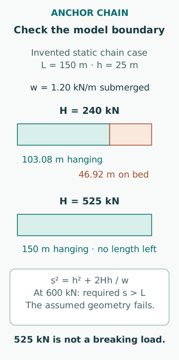
Take invented values w = 1.20 kN/m, h = 25.0 m, H = 240 kN and total chain length L = 150 m. The suspended length is sqrt(25² + 2×240×25/1.20) = 103.08 m. Thus 46.92 m remains available to lie on the bed in this model. Fairlead tension is 240 + 1.20×25 = 270 kN. None of these values represents a specified ship or chain.
The limiting horizontal tension when s reaches all 150 m is H = w(L² − h²)/(2h) = 525 kN. Asking the same horizontal-tangent model to carry 600 kN would require more chain suspended than exists. That is a model-validity failure, not a prediction that the chain breaks at 525 kN. Beyond it, a different geometry including a nonzero anchor-end angle is needed, along with the actual anchor and equipment limits.
Soil resistance is not recovered from chain geometry
The catenary calculation says what forces a stipulated chain shape would transmit. It does not say whether the anchor can resist them. Penetration and holding depend on seabed material, layering, obstructions, anchor condition and how load direction changes. A charted seabed description is useful context but does not measure the resistance of the exact patch occupied by the anchor.
A chain can be geometrically well arranged while the anchor is poorly engaged. Conversely, an anchor initially holding can lose resistance after a load-direction reversal or cyclic disturbance. Treat “the ship has not moved yet” as an observation over a particular interval, not a material test proving future holding capacity. No universal holding multiplier is assigned here.
Static balance does not describe snatch loading
Wind gusts, waves and vessel yaw change line demand. As geometric compliance is used up, a small additional ship displacement can produce a much larger tension increase. Energy is exchanged among ship motion, lifted chain weight, elastic stretch and fluid damping. A static mean force omits both the transient peak and the loading rate.
This is why dividing a breaking load by a chosen safety factor does not by itself establish anchoring suitability. The windlass, brake, stopper, chain, joining links, anchor and supporting structure form a load path with different functions. The approved arrangement determines which component carries sustained load. A classroom force model does not authorize an improvised transfer of load between them.
The swing envelope includes the hull
For a deliberately simplified geometric upper estimate, an inextensible straight 150 m chain spanning 25 m vertically has horizontal reach sqrt(150² − 25²) = 147.90 m. If the farthest relevant hull point lies 150 m from the fairlead, a fully aligned extreme gives about 297.90 m from the anchor. A hanging curve generally gives less horizontal reach than the straight line for the same length and height.
This is not a recommended anchor-watch radius. Anchor location uncertainty, vessel reference-point offsets, tidal changes, hull orientation, chain stretch and possible dragging all matter. Adjacent ships have their own swing geometry and may respond differently to wind and current. A circle around the GNSS antenna is not automatically the swept area of the entire hull.
Anchor-watch evidence needs more than one symptom
A change in position may reflect normal swing, sensor noise or dragging. A useful interpretation combines position history with independently observed ranges or bearings, heading, environmental changes and the vessel’s expected swing geometry. A low instantaneous SOG does not prove that the anchor holds, and a single position outside a chosen circle does not identify the mechanism without context.
MCA MGN 592 Amendment 2 emphasizes safe installation, inspection, maintenance and use of anchoring and related equipment. Its equipment guidance complements the geometric reasoning but does not replace vessel-specific anchor-watch and emergency procedures. Personnel exposure to loaded chain and machinery must remain part of the assessment, including during attempts to investigate an abnormal condition.
Keep the model’s boundaries visible
Common errors include using dry rather than submerged chain weight, equating water depth with fairlead height, assuming more chain always solves the problem, and treating an initially stationary ship as proof of permanent holding. Confusing a catenary lift-off limit with chain strength is another serious error.
A defensible study records seabed assumptions, geometry, load cases, equipment limitations and observation uncertainty separately. Its purpose is to explain what must be known and monitored. It does not prescribe chain length, an anchoring location, a weather threshold or a response to dragging for an actual vessel.
Sources
- Norcape: windlass damage, grounding and accident to person · UK MAIB · Source check date: 2026-10-06
- MGN 592 (M+F) Amendment 2 · UK MCA · Source check date: 2026-10-06