Knowledge / Navigation and marine safety
Bank effects and passing-ship interaction: pressure fields and control margin
Understand bank and passing-ship forces through pressure asymmetry, force moments, speed sensitivity and validation limits.
On this page
A ship near a bank or another hull moves through a flow field shaped by those boundaries. The resulting sideways force and turning moment can change rapidly with geometry. A useful explanation separates the physical mechanism from the evidence needed to predict a particular vessel.
The surrounding water is part of the manoeuvring system
A ship displaces water as it moves. Near a bank or another hull, the available flow paths become asymmetric and restricted, changing the pressure distribution over the hull. Ghent University’s bank-effects research overview identifies bank geometry, depth, separation, hull properties, speed and propeller action as important variables. Its commonly observed bank-attraction and bow-away description is a useful starting picture, not a universal force law.
The resulting response includes both lateral force and yaw moment. A ship can begin to rotate before a large sideways displacement becomes obvious. The pressure field also evolves as the hull passes a bank irregularity or another ship. Treating the bank as a constant sideways wind misses the coupling between position, speed, flow and the ship’s changing orientation.
Use depth and clearance ratios to describe the case
An absolute water depth means little without draught. For a fictional ship with draught T = 8.0 m in depth h = 10.0 m, h/T = 1.25 and static under-keel depth difference is 2.0 m. The same ship in 12.0 m gives h/T = 1.50 and 4.0 m difference. These ratios identify different confinement conditions; they do not assign a safe category.
Horizontal geometry matters too: bank slope, distance measured from the hull rather than the centreline, channel cross-section and the ship’s eccentric position. A rectangular channel width cannot fully describe a dredged trench beside a sloping shoal. State whether depth includes the relevant water level and whether the draught is static or affected by motion. Otherwise apparently identical simulations can represent different physical problems.
A speed-squared comparison has a limited purpose
For an illustrative force scale, write F = 0.5ρU²AC, with water density ρ, water-relative speed U, reference area A and a dimensionless coefficient C representing a specified geometry. If every other term is held constant, changing U from 6 kn to 8 kn multiplies the force scale by (8/6)² = 1.78. This shows sensitivity to speed; it does not provide the coefficient or actual bank force.
In a real constrained-water manoeuvre, C may change with depth, separation, trim, yaw and flow regime. Propeller and rudder conditions also change. Consequently, applying a square-law multiplier to one trial result cannot validate another condition. Ground speed alone is especially unsuitable where current changes the water-relative flow. A force scaling relationship should always name the quantities assumed unchanged.
Lateral force and turning moment are separate outputs
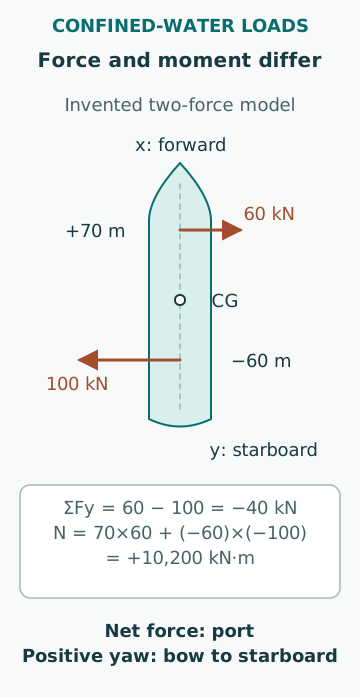
An original two-force model makes the distinction clear. Let x be forward from the centre of gravity and y positive to starboard. A 60 kN starboard force acts 70 m forward, while a 100 kN port force acts 60 m aft. Net lateral force is 60 − 100 = −40 kN, toward port. The yaw moment is 70×60 + (−60)×(−100) = 10,200 kN·m, positive under this defined convention.
The model can therefore produce a modest net sideways force and a substantial turning moment at the same instant. It does not describe a measured ship or typical pressure distribution. Its purpose is to show why cancelling net force does not necessarily cancel rotation. A complete manoeuvring model needs inertia, hydrodynamic derivatives, propulsion, rudder effects and time evolution as well as applied loads.
Passing ships create a moving pressure environment
MCA MGN 199, Dangers of interaction, April 2002 describes interaction during passing, close-company operations and shallow-basin manoeuvres. Its incident-based guidance emphasizes that the smaller vessel and assisting tugs can be particularly vulnerable. It is UK guidance and does not provide a universal minimum separation or an approved manoeuvre for every channel.
As bow, midbody and stern regions pass each other, the force and moment history changes. The response depends on relative longitudinal position as well as lateral spacing. A slowly overtaking vessel can remain exposed to this changing interaction for longer than a vessel in a quicker head-on encounter. That does not make higher speed a solution: force magnitude, available time and control capability all change together.
Duration and force need separate calculations
For a purely geometric example, define an interaction-study zone as 300 m of relative longitudinal travel. At 2 kn relative longitudinal speed, equivalent to 1.0289 m/s, traversal takes 291.6 s, or 4.86 min. At 4 kn it takes 145.8 s, or 2.43 min. The 300 m zone is invented and is not a physical boundary beyond which interaction vanishes.
This calculation describes exposure time only. It does not predict hydrodynamic load or recommend passing speed. A slower process can have lower instantaneous force but longer exposure, while a faster process can leave less time to identify unexpected yaw. A sound comparison considers both the load history and the vessel’s response history, rather than selecting whichever single metric looks more favourable.
The familiar bank-effect picture has exceptions
The author abstract for Lataire and colleagues, 2023, Boundary layer influence on ship model tests in extremely shallow and confined water reports a change from attraction to repulsion in some extremely shallow model-test conditions, linked to boundary-layer interaction. That finding is used here only to show that force direction is not universally fixed. The repository abstract was inspected; no numerical result from the full paper is used.
Scale effects matter because a model and a full-size ship cannot reproduce every nondimensional flow parameter simultaneously. A simulation fitted to one bank form and depth range needs evidence before extrapolation. A visually convincing replay does not establish that the force sign or magnitude is correct outside the validation envelope.
Control margin is conditional on the available system
A demanded rudder angle is not the same as achieved yaw control. Rudder inflow, propeller operation, speed through water, shallow-water effects and steering response determine the available action. Tug assistance has its own position, force-direction and safety limits. A comparison of nominal maximum forces omits the delay before those forces become available and the moments they create.
An educational assessment should therefore preserve the initial state, waterway geometry, interaction phase, control inputs and observed response. Note what changed before unexpected yaw began. Do not assume that deep-water trial data directly represent a confined channel, or that a previous successful passage proves the present one equivalent. Changes in loading, tide, bank profile or another vessel can invalidate that comparison.
Avoid a single-cause explanation
Bank effect, squat, current, wind and ship-to-ship interaction can coexist but are not interchangeable names. The useful question is which mechanism the observations support and how the available control was affected. Keep the speed reference and geometry with every numerical claim.
Common errors include treating all banks as vertical walls, assuming attraction always has one sign, using SOG in a water-flow scale, comparing force without moment and turning a model-test limit into an operating limit. The calculations here support physical understanding only. Qualified local assessment, vessel information and approved operating arrangements determine an actual manoeuvre.
Sources
- Bank effects research overview · Ghent University · Source check date: 2026-10-06
- MGN 199 (M): Dangers of interaction · UK MCA · Source check date: 2026-10-06
- Boundary layer influence on ship model tests in extremely shallow and confined water · Lataire, Raza, Vantorre and Delefortrie; Ghent University repository · Source check date: 2026-10-06