Knowledge / Navigation and marine safety
Emergency towing: connection load paths and dynamic loading
Trace emergency tow loads through lines, fittings and hull structure, while separating dynamic demand from nominal ratings and procedure readiness.
On this page
An emergency tow succeeds only if the entire connection can transmit the required changing load and can actually be deployed in the casualty condition. A strong rope is one element of that system. Load-path reasoning exposes the assumptions hidden by a single rating.
Separate towing arrangements from towing procedures
Emergency towing arrangements are the physical means of transmitting tow load; procedures explain how the ship’s actual resources can be used in the relevant emergency. Having a booklet does not create a suitable fitting, and having a strong fitting does not prove that it can be reached, rigged or used after loss of power. Both physical and operational readiness matter.
The IMO MSC 110 meeting summary, June 2025 records approval of MSC.1/Circ.1255/Rev.1 on preparing emergency towing procedures, alongside revised towing-equipment guidance. The older 2008 circular should therefore not be described as the newest guidance. The summary confirms the revision’s status; this article does not claim access to every detailed provision of the revised circular.
Check applicability before using a new requirement
IMO resolution MSC.549(108), adopted 23 May 2024 adds emergency-towing-arrangement requirements for ships other than tankers of at least 20,000 GT constructed on or after 1 January 2028, under its stated SOLAS amendment framework. This future construction-date scope must not be turned into a blanket retrofit statement for all existing ships in October 2026.
Tanker arrangements, existing shipboard procedures and later construction requirements are related but distinct subjects. A real applicability decision needs ship type, size, construction date, flag implementation and the approved documentation. The engineering examples below explain forces and evidence; they do not determine statutory compliance or replace the ship-specific emergency towing booklet.
Follow the load into the hull structure
The visible towline is only one part of the path. Load passes through its termination, joining components, chafing protection, fairleads or chocks, strongpoints and supporting hull structure. A strong rope cannot compensate for an unsuitable connection or a fitting loaded outside its intended direction. A marked safe working load must be read with its definition and configuration.
For a technical desk review, draw the path and identify the capacity evidence at each transition. Distinguish a line’s minimum breaking load from a fitting’s working-load rating and from a system design load. They cannot simply be sorted numerically to identify a weakest link. Condition, wear, corrosion, geometry and dynamic demand can alter the relevant capacity or load.
A fairlead can carry more than one line tension
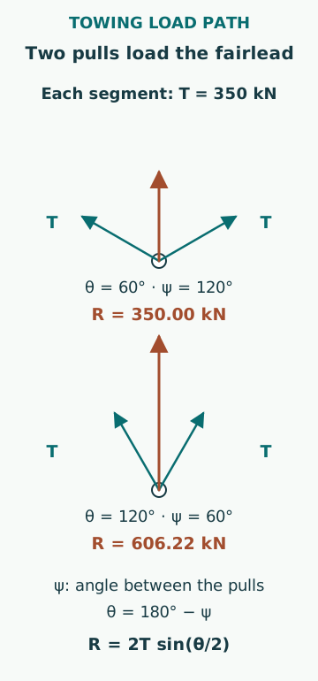
Assume a frictionless ideal fairlead redirects a line carrying equal tension T on both sides through a deflection angle θ, where zero means no change in direction. The resultant load magnitude on the fairlead is R = 2T sin(θ/2). This is vector addition of the two pulls exerted by the line segments. A drawing must define the angle; using the internal angle between segments without converting it gives the wrong result.
For an original T = 350 kN example, a 60° deflection gives R = 350 kN. A 120° deflection gives R = 606.22 kN. Friction, unequal tensions, three-dimensional lead and local bending are excluded. The example explains why a fairlead cannot be assessed from one rope-tension number alone; it is not a permissible lead-angle instruction.
Compliance changes the response to relative motion
A towline can accommodate relative motion through geometric sag, elastic extension and movement of the connected vessels. These mechanisms have different stiffness and damping. As sag reduces, the force required for further separation can rise sharply. A line that appears slack before a wave cycle can subsequently develop a high transient load.
For a deliberately simplified incremental spring model, take effective stiffness k = 600 kN/m and additional extension Δx = 0.40 m. The tension increment is kΔx = 240 kN. The additional quadratic elastic-energy term is 0.5kΔx² = 48 kJ. If pretension T0 already exists, total incremental work also includes T0Δx. The 48 kJ alone is therefore not the complete stored energy of a pretensioned towline.
Dynamic peaks cannot be inferred from mean pull
Wave encounter, vessel yaw, surge, towline material and length, winch behaviour and hydrodynamic damping influence the load history. A single multiplier applied to average tow resistance is not universally valid. Resonance or a sudden transition from slack to taut can create a different response from a smoothly varying load with the same mean.
A credible analysis states the sea conditions, vessel response model, towline properties, boundary conditions and validation evidence. Peak tension, loading rate and fatigue exposure are different outputs. A short calculation of mean resistance may support an initial comparison, but cannot demonstrate survival of the connection in a specified sea state. Uncertainty in the disabled vessel’s condition must also remain visible.
Loss of power changes what can be deployed
A plan that assumes powered winches, lighting, communications or hydraulic machinery must examine whether those services remain available in the emergency being considered. Access may be restricted by damage, fire, flooding, heavy weather or the vessel’s attitude. A connection that is strong in a drawing may be practically unreachable.
For a readiness review, separate available equipment, required personnel, communication paths and the information the assisting vessel needs. Confirm that the documented arrangement matches the actual ship and that modifications have not invalidated it. These are preparation questions, not instructions to expose crew on a hazardous deck or to improvise a connection during an emergency.
Personnel exposure follows the changing load path
MCA MGN 592 Amendment 2 addresses installation, inspection, maintenance and safe use of towing and related equipment. A useful general implication is that connection condition and people’s exposure must be considered together. A line can change direction, move across a deck or release stored energy if a component fails; a fixed painted boundary is not a complete model of every possible recoil path.
Communication should identify the actual state of the line and readiness of both ends, not merely that a message was transmitted. A command, acknowledgement, observed tension and observed vessel response are distinct events. Emergency release arrangements also have design-specific limitations and must not be assumed to function identically under every load direction.
A useful review preserves assumptions and unknowns
Common errors include equating bollard pull with all possible towline peaks, confusing breaking load with working load, ignoring force redirection and treating a procedural document as proof of hardware readiness. Another is quoting a new construction requirement without its date and ship scope.
The defensible output is an identified load path, compatible capacity evidence, stated dynamic assumptions and a list of readiness gaps resolved through the ship’s approved process. It does not select a tow speed, line length, connection point or rigging sequence for an unidentified casualty. Those require the actual vessels, conditions and competent towing assessment.
Sources
- MSC 110 meeting summary · IMO · Source check date: 2026-10-06
- MSC.549(108): SOLAS Chapter II-1 amendments · IMO · Source check date: 2026-10-06
- MGN 592 (M+F) Amendment 2 · UK MCA · Source check date: 2026-10-06