Knowledge / Navigation and marine safety
Parallel indexing: monitoring cross-track position with radar
Derive parallel-index geometry, interpret the sign of a deviation and distinguish cross-track monitoring from a complete position fix.
On this page
Parallel indexing turns an expected passing relationship into a continuous radar observation. Its strength is a simple geometric check; its weakness is that an incorrect reference can remain visually convincing. The following examples explain what the line measures and what it cannot establish.
The line expresses a geometric relationship
Parallel indexing compares a fixed radar echo with a line whose direction and offset come from the planned ground track. In MGN 379 Amendment 1, section 3.8, the UK MCA describes the technique as continuous cross-track monitoring and emphasizes that it does not replace position fixing or establish progress along the track. The line must be referenced to own ship: in true motion it must move with the vessel rather than stay painted on the screen.
The useful observation is whether the chosen echo follows the expected locus relative to own ship. The echo is not the ship’s position, and the index line is not a physical boundary painted on the sea. The method translates a charted spatial relationship into a directly observed radar relationship. Its independence from GNSS is valuable only when the target identity, chart geometry, radar ranging and heading reference are themselves credible.
Derive the perpendicular offset
For a local chart plane, define unit vector t along the planned track and unit vector n toward its starboard side. Choose any point p0 on that straight track. For a fixed target at q, the signed planned perpendicular offset is b = (q − p0)·n. A ship position p can be decomposed into along-track distance and signed cross-track displacement e = (p − p0)·n. Radar measures the target relative to the ship, r = q − p.
Taking the perpendicular component gives r·n = b − e. Thus e = b − r·n. This short derivation explains the apparent reversal: if own ship moves toward a starboard reference object, that object’s perpendicular distance decreases. It also explains why a range to the object is not automatically the index offset. Direct range in the horizontal plane includes the along-track component and changes while a correctly positioned ship passes.
A signed example prevents wrong-way interpretation
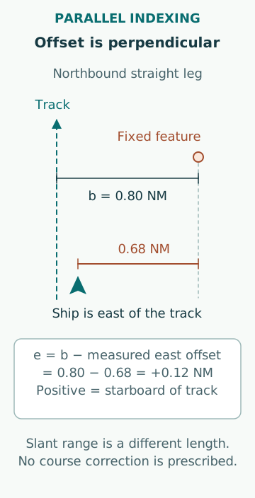
Consider an invented northbound track along east coordinate zero. A fixed headland is 0.80 NM east of the track, so b = +0.80 NM. Initially its radar position is 0.80 NM east and 1.20 NM north of own ship. Its range is sqrt(0.80² + 1.20²) = 1.442 NM, yet the correct cross-index offset is 0.80 NM. Using 1.442 NM as the offset would encode the wrong geometry.
Later, the headland’s measured east component is 0.68 NM. The inferred cross-track displacement is e = 0.80 − 0.68 = +0.12 NM, or 222.24 m to starboard of the planned track. This does not mean “turn port now”: other traffic, available water, vessel response and the whole navigation situation remain outside this calculation. It means the observed relationship differs from the planned one by a stated signed amount.
Choose a feature with a stable echo identity
A prominent point on a chart is useful only if the radar return can be associated with that same feature. A headland can present a broad or changing leading edge as aspect changes. A charted shoreline may be a tidal boundary rather than the elevated face producing the strongest echo. A buoy may swing around its mooring; a vessel apparently at anchor may drag or manoeuvre. Each creates a different error mechanism.
For a classroom preparation, document the feature, the specific echo edge being used, the intended observation sector and the reasons that the relationship is stable enough. Compare alternatives with different geometries. A second reference can reveal inconsistent identification, but two points on the same poorly surveyed shore may share chart errors. More lines do not automatically create independent evidence.
Heading and line-angle errors grow with distance
An angular error can appear as a cross-track error even when radar range is correct. For a small orientation error δ, the first-order perpendicular error is approximately the along-track target separation multiplied by δ in radians. At an along-track separation of 2.0 NM and a 1° error, that term is about 2.0 × π/180 = 0.0349 NM, or 64.65 m. The sign depends on the geometry.
This is not the radar’s stated total accuracy. It is an original sensitivity calculation showing why a distant reference can magnify a small angle error. Include charted feature uncertainty, echo selection, range and bearing errors, line-setting error and the reference point used on the vessel. Combining all terms by root-sum-square would require justified statistical independence and comparable uncertainty definitions; otherwise it can create an unjustifiably small number.
The vessel origin and display mode matter
MSC.192(79), sections 5.9 and 5.16, addresses a consistent common reference point, antenna offsets and parallel-index facilities. The geometric origin used for a distance must match the origin assumed in planning. A radar antenna forward of the conning position, or a selected alternative antenna, can otherwise produce a systematic discrepancy. The existence of an offset setting does not prove it contains the correct value.
Changing range, off-centring, orientation or motion mode should leave the intended physical relationship understandable. Electronic lines may preserve their numerical offsets while an old reflection-plotter line is tied to one scale. A stored line can also be correct for the previous leg and wrong for the current one. Demonstrating a preset before use is more informative than recognizing a familiar line number.
A straight-leg monitor does not describe a turn
For a straight planned leg the target’s expected relative locus is a straight line. During a turn the ship’s intended cross-track relationship changes continuously, so extending the old line through the manoeuvre does not define the planned curved track. A proper teaching diagram marks where each straight-leg construction applies and where a different monitoring arrangement is needed.
Parallel indexing also lacks a unique along-track coordinate. Several ship positions along the same track produce the same perpendicular offset. A vessel can therefore be correctly aligned with a line but already beyond an intended waypoint. Time, independent fixes, additional ranges and the passage plan provide different information; they cannot be replaced by the reassuring sight of an echo on its index.
Use disagreement as information
If GNSS-derived cross-track error and the radar index disagree, preserve both observations and their timestamps. A useful desk exercise tests separate hypotheses: wrong line, wrong target, changed reference origin, heading error, chart displacement and position-source error. Predict what each hypothesis would do to another fixed echo or an independent range. This converts an argument between displays into an evidence comparison.
Common errors are using radial distance as perpendicular distance, losing the sign convention, mistaking a moving reference for a fixed one, retaining the previous leg’s preset and assuming a matched line validates the entire route. A credible record states the selected reference, planned offset, observed difference, uncertainty and limits of the inference. Operational response belongs to the qualified bridge team and the vessel’s procedures.
Sources
- MGN 379 (M+F) Amendment 1 · UK MCA · Source check date: 2026-10-06
- MSC.192(79): Radar performance standards · IMO · Source check date: 2026-10-06