Knowledge / Navigation and marine safety
Radar shadow sectors: installation geometry and the meaning of no echo
Relate radar shadow geometry to detection gaps, clutter, correlated missed scans and the evidence needed to verify actual coverage.
On this page
A radar can work normally in one direction while providing weak coverage in another. Structural obstruction, clutter and target properties affect different parts of the detection chain. Understanding those mechanisms makes the absence of an echo a more carefully bounded observation.
A blank sector can be an installation effect
A radar antenna needs an adequate propagation path to and from a target. Masts, funnels, cranes and other structures can obstruct or attenuate that path. A blind sector suggests severe loss of coverage; a shadow sector can involve reduced performance rather than complete absence of returns. The exact result depends on the installation, target direction and height, frequency, diffraction and reflections.
MCA MGN 379 Amendment 1, section 3.4 advises awareness of blind and shadow arcs and a diagram updated when changes affect them. This is practical installation-evidence advice in UK guidance, not a universal geometric formula for detection. A healthy transmitter and a bright coastline elsewhere on the display do not prove adequate coverage behind an obstruction.
Use geometry to identify a question, not certify coverage
For a simplified plan view, an opaque obstruction of width w at distance d from the antenna centre subtends angle θ = 2 atan(w/(2d)). An invented 1.0 m obstruction 10.0 m away gives θ = 5.72°. At a target-plane distance of 2 NM, the ideal width is 2R tan(θ/2) = 370.4 m. The calculation uses a point antenna and straight rays.
Real antennas have finite dimensions and beam patterns. The obstruction may not span the target’s elevation, and diffraction or reflected paths can produce weak or displaced returns. Therefore the 5.72° is a geometric estimate for investigation, not a certified blind-sector width. Installation survey, manufacturer guidance and appropriately controlled performance evidence determine actual coverage.
A target can remain hidden for a meaningful interval
Continue the ideal geometry with a target moving transversely across the 370.4 m width at relative transverse speed 12 kn, or 6.1733 m/s. The crossing time is 60.0 s. This assumes a straight path perpendicular to the sector centreline at nearly constant range, a point target and no own-ship rotation. A different path or changing heading changes the interval.
The result is not a tracking-coast allowance or a safe period without observation. It shows that a modest angular obstruction can correspond to substantial unobserved motion. The target may turn while hidden, and a tracker may continue to draw a predicted symbol even when no fresh echo supports it. A displayed track and a current detection are different evidence states.
Clutter and obstruction are different mechanisms
Sea clutter consists of returns associated with the sea surface, while precipitation can create additional echoes and attenuation. A structural shadow limits the propagation path. These mechanisms can overlap, but adjusting a clutter control cannot remove a physical obstruction. Conversely, a clear geometric line of sight does not guarantee that a weak target stands out from clutter.
IMO MSC.192(79), section 5.3 separates detection in specified clear conditions from degraded performance in clutter. Its test conditions and target assumptions are not a guarantee that every real object will be detected at the tabulated range. The standard also requires explanation of relevant processing limitations. An operational interpretation must retain those conditions instead of quoting a range alone.
Target strength changes with aspect and structure
Radar cross-section is an electromagnetic scattering property, not simply the vessel’s physical area. Material, shape, orientation, height, sea state and multipath influence the return. A small craft can appear intermittently, and a large vessel’s effective reflecting point can shift. An echo disappearing for a few scans does not uniquely identify a shadow sector.
A useful diagnosis asks whether the loss repeats at a consistent antenna-relative bearing, whether several targets are affected, whether it depends on range or weather and whether another antenna sees the same object. These patterns support different hypotheses. Keep raw detection evidence separate from target-tracker behaviour, since filtering can smooth both genuine intermittency and a developing coverage problem.
Repeated scans are not always independent trials
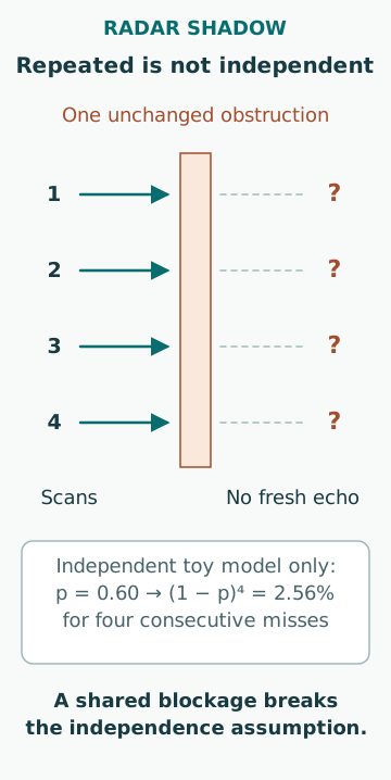
In an original probability toy model, assume a target has independent detection probability p = 0.60 on each scan. The probability of missing it on all four scans is (1 − p)^4 = 0.0256, or 2.56%. Those assumptions are intentionally strong and the value is not measured radar performance. They show how repeated independent opportunities can improve detection.
A persistent structural blockage violates independence: the same obstruction can affect every scan. A slowly changing sea-clutter pattern can also correlate missed detections. It is therefore wrong to use the toy formula to claim that enough rotations make a shadowed sector reliable. Repetition supplies new evidence only to the extent that the detection opportunity actually changes or provides independent information.
Two radars need a real coverage comparison
Different antenna positions can provide complementary views, but they can also share a broad obstruction or other dependencies. Different frequency bands do not automatically create different structural coverage. A comparison should identify each antenna’s position, height, shadow diagram, selected mode and performance state. A second screen connected to the same antenna adds no new propagation path.
Check whether an apparent mismatch arises from antenna-reference offsets, range settings, processing or target association before concluding that one radar has failed. The relevant question is what additional evidence the second installation supplies in the sector of interest. Equipment count is an inventory fact; demonstrated complementary coverage is a performance claim.
Installation changes can invalidate an old diagram
A crane in another stowed position, added deck cargo, a new mast fitting or changed antenna location can alter obstruction geometry. A diagram created at commissioning may no longer represent the operational arrangement. The review must therefore connect the recorded coverage with the current configuration and relevant movable structures.
An appropriate controlled verification records target characteristics, bearings, ranges, weather, radar settings and which antenna was used. It should state what was tested and what remains unverified. A strong test reflector in one sector cannot prove detection of every weak small craft elsewhere. Maintenance tests and navigation observations have different evidential scopes and should be described accordingly.
Interpret no echo as a bounded observation
Common errors include treating a blank area as empty water, assuming a successful performance-monitor test validates every bearing, counting predicted symbols as fresh echoes and using independent-scan probabilities for a persistent obstruction. Another is tuning solely for the cleanest picture and losing weak-target information.
The useful conclusion states which directions and conditions are supported by evidence, what can impair detection and how complementary observations contribute. It does not prescribe radar-control settings or a manoeuvre to expose a hidden sector in live traffic. No echo means no detected return under the current observation conditions; it does not prove that no object exists.
Sources
- MGN 379 (M+F) Amendment 1 · UK MCA · Source check date: 2026-10-06
- MSC.192(79): Revised radar performance standards · IMO · Source check date: 2026-10-06