Knowledge / Navigation and marine safety
Tug assistance: bollard pull, force direction and effective turning moment
Translate towline tension into useful force and yaw moment, with unit conversion, three-dimensional geometry and tug safety limits.
On this page
Tug assistance is a force applied at a place and in a direction. Bollard pull alone leaves both of those out. Explicit component and moment calculations explain why nominally similar assistance can produce very different ship responses.
A certificate is one part of the force story
Bollard pull characterizes a tug’s pulling capability under specified test conditions, typically at essentially zero advance speed. It is not a promise that the same force will act in every direction at the assisted ship throughout a manoeuvre. Tug type, operating mode, water-relative speed, propulsor loading, depth, towline geometry and environmental conditions change the usable assistance.
The UK Guide to Good Practice on Port and Marine Facilities, updated 15 April 2025, towage guidance links tug provision to vessel size and characteristics, berth, conditions and available tug capability. It is port-management guidance, not a universal tug-number formula. An actual operation needs the applicable port requirements and the current vessel/tug limitations, including any defects or unavailable equipment.
Convert force units before projecting them
In tug discussions, “tonnes of pull” usually means tonne-force rather than mass. One tonne-force corresponds to 9.80665 kN under standard gravity. An illustrative 50 tf is therefore 490.3325 kN, or 490.3 kN when rounded to one decimal place. Writing 50 tonnes as though it were 50 kN understates force by nearly a factor of ten.
The conversion does not establish available towline tension. A nameplate, certificate, measured towline load and commanded engine setting describe different things. An engine percentage is not generally a linear percentage of line force. Retain the source and conditions of each value before combining them. Force calculations should also distinguish continuous capability from a short-duration maximum if the source does so.
Project the line force in three dimensions
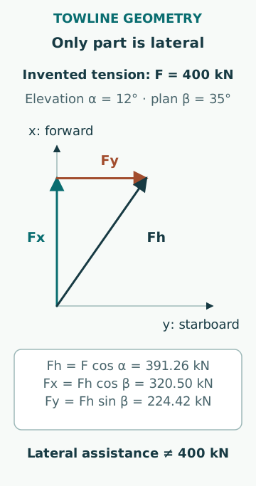
For an original geometry example, assume towline tension F = 400 kN, elevation α = 12° above the horizontal and horizontal angle β = 35° from the ship’s forward axis toward starboard. With x forward, y starboard and z upward, Fx = F cos α cos β = 320.50 kN; Fy = F cos α sin β = 224.42 kN; Fz = F sin α = 83.16 kN. The total horizontal force is 391.26 kN. These translational component directions are separate from the signed yaw scalar defined below.
Only Fy contributes directly to starboard translation in this coordinate description, although every component can matter to fittings and structure. Treating all 400 kN as lateral assistance overstates that component by 175.58 kN. The selected angles and tension are fictional and are not a recommended tug position. Changing line lead changes both useful force and loads in the connection.
Moment depends on the full lever arm
Define the signed yaw scalar N as positive for a turn of the bow toward starboard. For a horizontal force applied at position (x, y) relative to a chosen ship reference, N = xFy − yFx. Its positive direction corresponds to the downward vertical axis in Fossen’s conventional forward/starboard/down frame, section 4.1; the axial moment along the upward z defined above is −N. If the previous force acts at x = 75 m forward and y = 10 m starboard, N = 75×224.416966 − 10×320.500643 = 13,626.27 kN·m, or 13.63 MN·m. Retain unrounded components until the final result.
Using only 75×Fy gives 16.83 MN·m and misses the opposing contribution from the longitudinal component acting off the centreline. If the reference point changes, the quoted moment changes even though the physical force does not. State whether moments are about the centre of gravity or another point. A force diagram with an unlabeled pivot can be numerically correct yet physically ambiguous.
Two tugs can create translation, rotation or both
Assume two fictional purely lateral forces of 200 kN each, acting 70 m forward and 70 m aft of the centre of gravity. If both act to starboard, net lateral force is 400 kN and their yaw moments cancel in this symmetric idealization. If the forward force acts starboard and the aft force port, net lateral force is zero while the signed yaw couple is N = +28,000 kN·m, or +28.0 MN·m, toward starboard.
This comparison explains why adding bollard-pull ratings cannot describe turning capability. Equal total force can be arranged with very different moments, and equal nominal tugs may not deliver equal forces in different operating conditions. Actual motion also depends on hull resistance, added mass, yaw inertia, rudder and propeller action. A static force balance is not a prediction of turning rate or stopping distance.
Environmental demand has its own geometry
Wind load depends on projected area, relative wind, drag behaviour and its centre of pressure. Current load depends on underwater geometry and water-relative flow. Two equal lateral environmental forces can demand different tug moments if their centres of action differ. A large freeboard can increase wind demand while loading changes the underwater response at the same time.
A conceptual wind-force scale proportional to speed squared implies that, with unchanged area and coefficient, increasing wind speed from 12 to 15 m/s multiplies the scale by 1.5625. This is a sensitivity ratio, not a wind limit or tug requirement. Gusts, shielding, direction changes and uncertain coefficients mean that a simple mean-force calculation cannot establish the available operational margin.
The tug’s safety limits remain part of the system
The MAIB Biter/Hebridean Princess report 17/2024, section 1.4.6 and analysis explains girting through towline and hydrodynamic forces that can generate a capsizing moment. The case demonstrates why the assisted ship’s desired force cannot be considered separately from the tug’s stability and control. Its circumstances do not establish a universal speed limit for other tugs.
Towline release, towing-point arrangement and crew communication have specific designs and operating limits. The load that is useful for the ship may be unsafe for the tug in another orientation. A numerical calculation cannot authorize altering a release system, moving a towing point or improvising rigging. Those require the actual approved arrangement and competent operational assessment.
Trace the connection and the delivered response
Line tension passes through fairleads, fittings and supporting structure. A rating may depend on direction, lead and the number of loaded parts. The weakest relevant element cannot be identified by comparing labels with different definitions. Dynamic loading, chafe and line condition can further constrain the system even when the nominal pull is acceptable.
A useful review therefore separates requested assistance, available tug capability, transmitted line force, structural capacity and observed vessel response. Record how changes are communicated and confirmed. A tug command being acknowledged does not prove the required force has developed at the ship, and a force being measured does not prove the expected yaw response has occurred.
Use calculations as a transparent comparison
Common errors are adding tug ratings without direction, using the full line force as lateral force, ignoring line elevation, choosing an undefined moment centre and treating a static certificate as dynamic performance. Preserve unrounded intermediate values and state the force-unit convention.
The useful deliverable is a force-and-moment explanation with explicit assumptions and identified missing evidence. It can support a briefing or technical study, but it does not select tug positions, towing speeds, connection arrangements or abort criteria for a real manoeuvre. Those decisions require the vessel, tug, port and environmental context together.
Sources
- A guide to good practice on port and marine facilities · UK Department for Transport/MCA · Source check date: 2026-10-06
- Girting and capsize of Biter while assisting Hebridean Princess · UK MAIB · Source check date: 2026-10-06
- A Nonlinear Unified State-Space Model for Ship Maneuvering and Control in a Seaway · Thor I. Fossen, Norwegian University of Science and Technology · Source check date: 2026-10-07