Knowledge / Risk analysis methods
From LOPA to a safety function: reduction target, specification and SIL verification
Carry an original risk-reduction allocation through a physical isolation requirement and a bounded hardware calculation, while keeping target integrity separate from demonstrated integrity.
On this page
A LOPA worksheet can identify how much additional risk reduction is needed, but the resulting number does not specify a complete safety instrumented function. It does not tell a valve how fast to close, prove the sensor sees the dangerous state, or establish the systematic capability of the installed design. The handoff needs a chain from scenario and target, through a testable safety requirements specification, to separate evidence for performance and integrity.
Keep four different outputs distinct
HSE’s functional-safety guidance separates risk allocation, specification, implementation, validation and assessment within the safety lifecycle. For this example, retain four explicit outputs: the required risk reduction, the safety requirements specification (SRS), the calculated random-hardware performance, and the conclusion supported by the complete integrity evidence. Each answers a different question.
A target states what the design must achieve. A specification states what it must do and under which conditions. A calculation estimates performance under an explicit model. A justified integrity conclusion also depends on whether the implemented function, architecture and lifecycle evidence satisfy the applicable requirements. Using the same phrase “SIL achieved” for all four hides unfinished work and can make an unverified component selection appear to close a scenario.
Carry the exact scenario and credit boundary into allocation
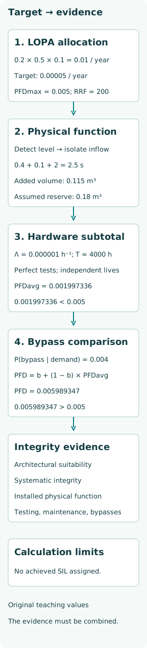
Consider an invented receiver-overfill scenario initiated by failure of normal filling control at 0.2 events/year. Let the conditional exposure factor be 0.5 and the failure probability of an already credited protective layer be 0.1 for that scenario and exposure. Before the proposed new function, the corresponding scenario frequency is 0.2 × 0.5 × 0.1 = 0.01/year. These are stipulated teaching inputs, not industry default credits.
The existing layer must actually address the stated consequence, and the exposure factor must not repeat a condition already included in the initiating frequency. Keep the new function out of the credited-layer product until it is allocated and verified. If normal control, the old layer and the new function share a failure mechanism, that dependence must be represented rather than hidden in a multiplication of marginal probabilities.
Calculate the numerical target without certifying a design
Choose a scenario-frequency target of 0.00005/year solely for this example. The new function’s allocated maximum failure probability is PFDmax = 0.00005/0.01 = 0.005, corresponding to required risk reduction 200. This uses a low-demand formulation and the relevant failure probability conditional on the remaining demand scenario. The chosen frequency criterion is not a universal risk-tolerability rule.
Translating that allocation into a SIL target requires the applicable standard, demand mode, function boundary and project criteria. A low-demand average probability and a dangerous-failure frequency per hour are different measures; changing the units in a spreadsheet does not convert one into the other. The example retains the explicit 0.005 requirement rather than awarding an integrity label from one numeric comparison.
Specify the physical action and its acceptance conditions
HSG238 distinguishes the required safety action from its integrity requirement. For the hypothetical receiver, define the proposed function as detecting the specified high-level condition, closing the independent transfer-isolation valve, and retaining isolation until an authorized reset after the initiating condition is resolved. A relay output changing state is not the required physical result; inflow must be interrupted as specified.
The SRS for this case needs a defined sensing location and valid measurement range, the detection condition and its uncertainties, the isolated state, the relevant transfer modes, permitted response time, reset behavior and what happens on loss of power or invalid measurement. It must also make the testing, bypass and restoration assumptions usable by design and operations. A label such as “high-level trip, PFD 0.005” leaves those essential behaviors unspecified.
Turn response time into an independently checkable volume budget
Assume 0.18 m³ of usable receiver volume remains at the defined detection condition. Bound inflow by 0.03 m³/s until isolation is complete, with a further 0.04 m³ of line drainback afterward. Allocate worst-case detection, logic and completed valve-isolation delays of 0.4, 0.1 and 2 s. Total response is 2.5 s, so additional volume is bounded by 0.03 × 2.5 + 0.04 = 0.115 m³.
The remaining volume margin is 0.065 m³. The same balance gives maximum response time (0.18 − 0.04)/0.03 = 4.666667 s under these assumptions. This is a physical check separate from PFD: a perfectly reliable valve that closes too late would fail the specified function. Real evidence must substantiate usable volume, sensor delay, worst inflow, valve motion and residual drainage, including measurement uncertainty and other inflow paths.
Evaluate one narrowly defined random-hardware model
For an illustrative series-required sensor, logic solver and final element, stipulate hidden dangerous failure rates of 0.0000004, 0.0000001 and 0.0000005 h⁻¹. Their lifetimes are independent and exponential; all start healthy and undergo simultaneous perfect testing and immediate restoration every 4000 h. Relevant demand age, conditional on no bypass, is uniform and independent of those lifetimes. Repair delay, test downtime, uncovered modes, actuation failures, common cause and systematic failures are excluded.
The NRC Fault Tree Handbook relates perfect periodic tests and uniformly timed demands to interval-average latent unavailability. Here Λ = 0.000001 h⁻¹ and q(t) = 1 − exp(−Λt), since all three elements are required. Integrating over the common interval gives PFDavg = 1 − [1 − exp(−ΛT)]/(ΛT) = 0.001997336. The small-rate approximation ΛT/2 gives 0.002. Average the joint function state; multiplying separately averaged component availabilities would lose the shared test-age dependence.
Show why a passing subtotal can still miss the allocation
The limited hardware result is below the allocated 0.005. Under the original scenario factorization it corresponds to residual frequency 0.00001997336/year and a hardware-only reduction factor about 500.667. That statement is conditional on the model and data; it neither includes every unavailability source nor demonstrates that the physical function will be delivered in time.
As a separate comparison, stipulate that the function is bypassed at 0.004 of the relevant demand times, and that its hardware-failure probability when not bypassed is the calculated average. During bypass it cannot protect. Total failure probability is then 0.004 + 0.996 × 0.001997336 = 0.005989347, giving residual frequency 0.00005989347/year, above the chosen target. The 0.004 is a demand-conditioned probability, not a time fraction silently assumed independent of operating disturbances.
Verify architecture and systematic integrity on their own terms
HSE’s control-system guidance distinguishes random-hardware defenses, architectural considerations and measures against systematic or common-mode failure. The series calculation does not show that a selected architecture is permitted for the target, that component evidence applies to the environment, or that common dependencies are controlled. Those conclusions require their own documented assessment using the applicable requirements.
IEC’s official consolidated IEC 61511-1 publication covers process-industry SIS specification, design, installation, operation and maintenance. Check the project’s applicable edition and requirements, including architecture and systematic-capability evidence, rather than treating this public scope description as a clause-by-clause assessment. A component certificate can support defined claims under its stated conditions; it cannot by itself certify the assembled receiver function or its application program.
Validate the complete requirement and maintain the assumptions
Create a trace from each SRS requirement to a design item and a verification or validation result. For this receiver, evidence should cover the physical isolation and volume budget, signal scaling and fault responses, latching and reset, relevant transfer modes, and the approved test and restoration sequence. Tests must be designed so they do not create an actual overfill. A simulated input can verify logic while leaving the sensor connection or final valve untested.
The assumed complete proof test must be supported by the modes it can reveal. Partial coverage, overdue tests, repairs and bypasses change the calculation boundary. Record actual failures and demands so that departures from the assumed rates, modes or operating conditions become visible. A good initial calculation cannot preserve its own validity when equipment, firmware, test procedures or process duty changes.
Close the allocation with a precise evidence statement
The defensible result for this teaching case is narrow: the chosen scenario requires PFD no greater than 0.005; the specified volume assumptions allow a bounded 2.5 s response; the idealized random-hardware subtotal is 0.001997336; the separate bypass comparison increases it beyond the allocation. Architecture, systematic integrity, real failure data and installed-function validation have not been established by those numbers.
A real handoff should name the function and SRS revision, list the target and verified performance measures, link the supporting design and test evidence, and resolve or explicitly carry outstanding constraints to the responsible decision. Acceptance follows the complete evidence and applicable lifecycle process. The purpose of LOPA is to make the remaining requirement explicit; the purpose of verification is to show that the specified, implemented function actually meets it.