Knowledge / Machinery and energy
Boiler drum level: shrink, swell and the limits of a level signal
Distinguish drum inventory from a moving water–steam mixture, follow a mass-deficit example and see how density compensation and three-element control address different problems.
On this page
A rising boiler drum level does not always mean that water mass is increasing. Pressure and heat-release changes can alter the volume of steam bubbles beneath the visible surface. Meanwhile, the instrument that reports level can have its own density-dependent error. These are two different problems: a real change in the mixture’s occupied volume and an error in converting a measurement into height. Keeping them separate is essential when interpreting a fast change in steam demand.
Define level and inventory as different quantities
Level is a height relative to a reference. Inventory is a mass within a stated boundary. In a boiling system, liquid and vapour occupy that boundary together, and their relative volumes can change rapidly. A particular indicated height cannot therefore be converted into water mass with one fixed litres-per-millimetre factor across all operating states. Drum geometry and phase distribution matter.
The upper surface of a bubbly mixture can move even if there is no corresponding increase in total mass. Calling this an apparent level rise means apparent additional inventory; it need not mean the sensor invented the surface motion. Conversely, a faulty density correction can distort the indicated height even when the actual mixture level is unchanged. An investigation should identify which mechanism, or combination, is relevant.
Explain swell and shrink through the pressure change
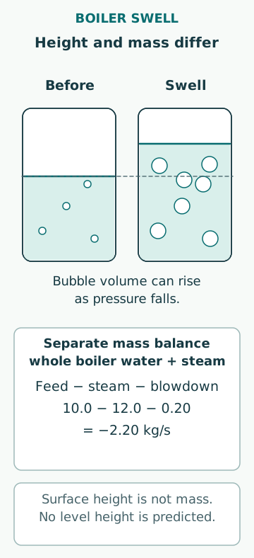
Spirax Sarco’s level-control explanation describes how a sudden steam demand and falling pressure can expand bubbles and flash some water, producing swell. A simple level-only response can then reduce feed at a time when additional mass is needed. The reverse volume response, shrink, can occur when bubbles collapse under changed conditions. These are process dynamics, not proof that a transmitter has failed.
The exact response depends on boiler type, firing, circulation, pressure and the time scale of the disturbance. Do not assign a universal swell height or duration. Cold feedwater and other heat-balance changes can also affect bubble behaviour. A useful interpretation links level, pressure, steam flow and feed flow in time, instead of reading each trend in isolation or assuming every rise calls for the same manual correction.
Use a mass balance to expose the counterintuitive case
Consider a simplified total boiler water-and-steam boundary with feed entering at 10.0 kg/s, steam leaving at 12.0 kg/s and blowdown leaving at 0.20 kg/s. Neglect leaks and other streams. Total mass changes at dM/dt = 10.0 − 12.0 − 0.20 = −2.20 kg/s. If these rates persisted for 60 s, the boundary would lose 132 kg. That statement follows from conservation of mass regardless of whether the mixture surface temporarily rises.
This is an invented accounting example, not a dynamic simulation or a permitted operating interval. It does not predict how many millimetres the drum level moves or when a protection acts. Those outcomes require geometry, initial state, circulation and heat-transfer behaviour. The example is useful because it demonstrates exactly what a level trace alone cannot establish: the sign of the short-term inventory change during a two-phase transient.
Distinguish level, steam flow and feedwater flow
A conventional three-element strategy uses drum level, steam flow and feedwater flow. Yokogawa’s 2014 application note describes a typical cascade arrangement in which the level controller works with a feedwater-flow controller. Steam demand provides information about the outgoing load; measured feed flow provides evidence of what actually enters. A valve-position signal cannot replace that flow measurement when the pressure available across the valve varies.
Level feedback corrects the longer-term inventory tendency and unmeasured mismatch, while flow information can help respond before level alone provides a useful signal. The exact architecture and compensation are equipment-specific. Three signals do not automatically constitute three independent protective layers: they may share a controller, power source or configuration error. Control performance and safety protection require separate assessments.
Recognize low-flow and mode-transition limitations
At startup or very low load, a flow transmitter may be below its reliable measurement range. A value displayed with several decimal places is not necessarily a valid control input there. The cited Yokogawa note specifically discusses the need to consider single-element operation under startup conditions with inadequate flow measurement. It does not establish a universal crossover percentage or a transferable switching sequence.
A transition between modes should avoid a discontinuity in valve demand and must preserve the intended protection. An analysis can ask whether the measured flows are valid, whether controller states match and whether a failed signal is clearly identified. It cannot infer a safe tuning constant from a generic diagram. Document the actual mode logic and the evidence from the approved commissioning or test process.
Understand the hydrostatic measurement model
A differential-pressure level measurement depends on the liquid and vapour densities and on the reference-leg arrangement. Emerson’s calibration note explicitly distinguishes height from differential pressure and includes both saturated-water and steam density. Drum pressure may cancel as a common static term, yet its effect on fluid density does not disappear. The reference leg also has its own temperature and density conditions.
As an isolated teaching model, suppose reference-leg effects have already been removed and a 0.500 m height produces Δp = (ρliquid − ρvapour)gh. With assumed densities 800 and 30 kg/m³, and g = 9.81 m/s², Δp is about 3.777 kPa. If software incorrectly uses a liquid density of 900 kg/m³ while retaining the same vapour density, it would infer about 0.443 m. This illustrates an approximately 57 mm error from the chosen mismatch, not a calibration formula for an actual installed wet-leg system.
Keep compensation separate from protection
ISA’s public description of TR77.42.02 identifies compensated differential-pressure drum-level measurement as a dedicated technical subject. A pressure-dependent calculation can improve the interpretation of a valid signal, but it cannot repair a blocked connection, an unsuitable reference leg or an incorrectly identified pressure input. No paid full standard was required to establish that limited scope statement.
Likewise, a sophisticated control loop does not replace the applicable low-water or high-level protective functions. A high level can contribute to carry-over, while inadequate water coverage can expose heated parts to damage. The required devices, independence and actions are set by the boiler’s applicable regime and approved arrangement. Treat a protective trip or inconsistent level indication as a condition governed by that arrangement, not as an invitation to bypass it because a model predicts swell.
Read a time-aligned event record
For a demand-change event, record level from the available independent indications, drum pressure, steam flow, feedwater flow, feed-valve demand and position, firing state and the active control mode. Include timestamps, sampling intervals and known filtering. A slow averaged trend may hide a short reversal, and a time offset between channels can make a response appear to precede its cause.
Compare whether the flow balance and pressure change explain the direction of the level movement. Then test whether the instrument model and actual reference conditions are consistent. If these accounts disagree, keep both a process explanation and an instrument explanation open. A diagnosis is stronger when it predicts another observable consequence and that consequence is checked, rather than when it merely labels a trace “swell.”
Make the conclusion useful without overclaiming
A clear conclusion states the inventory boundary, the phase-volume mechanism, the measurement principle, the active control strategy and any unresolved signal validity. It should distinguish a verified cause from a plausible explanation. If changes to instrumentation or control are proposed, the relevant review must include startup, normal load, transients, signal failure and restoration from test conditions.
The central lesson is that height, mass and measurement validity are separate quantities. Flow balance answers an inventory question, phase behaviour explains shrink and swell, and instrument modelling explains how the signal represents height. Combining those views gives a useful engineering interpretation while leaving operating actions and protective limits with the actual boiler documentation.
Sources
- Automatic level control systems · Spirax Sarco · Source check date: 2026-10-06
- Boiler Drum Level Control, 2014 · Yokogawa · Source check date: 2026-10-06
- Boiler Drum Level Transmitter Calibration, 00840-0100-4360 Rev BB, September 2026 · Emerson / Rosemount · Source check date: 2026-10-06
- ISA-TR77.42.02-2014: Compensated Differential Pressure Based Drum Level Measurement · International Society of Automation · Source check date: 2026-10-06