Knowledge / Machinery and energy
Centrifugal fuel separation: density, viscosity and interface control
Use a bounded settling calculation to understand particle-size sensitivity, then separate oil–water interface behaviour, throughput and sampling evidence from the claim that a running separator is cleaning effectively.
On this page
A fuel separator can be rotating at the expected speed while delivering unsatisfactory cleaning. Rotation supplies the centrifugal field, but separation also depends on the difference in phase density, viscosity, particle or droplet size, flow path and time available. An oil–water interface must also remain in the appropriate region for the installed design. Evaluating those conditions gives a better explanation of separator performance than simply confirming that the motor is running.
Distinguish separation from filtration
A centrifugal separator uses density differences between phases; a filter relies on a different capture mechanism. GEA’s separator overview distinguishes liquid–liquid, liquid–solid and combined separation applications. A marine fuel-treatment chain may use several mechanisms because one stage does not perform every required task. Dissolved constituents, stable very fine dispersions and solids of different sizes do not all respond identically.
Name what must be removed and how success is measured. A water-content signal is not a direct measurement of all abrasive particles. A nominal filter rating is not a separator efficiency. A visually clear sample is not proof that small damaging contaminants are absent. The relevant quantity may be water, a specified particle population or an elemental concentration, and those measures must not be silently exchanged.
Read the local settling relationship
CIMAC’s 2024 fuel-cleaning guideline gives the centrifugal Stokes relationship vc = d²(ρp − ρf)ω²r/(18μ). Here d is particle diameter, ρp − ρf the density difference, ω angular speed, r radius and μ dynamic viscosity. It explains why small particles and viscous fuel are harder to separate. The equation is a bounded physical model, not a complete separator-capacity calculation.
Use it for an isolated approximately spherical particle under low-Reynolds-number settling assumptions. Actual disc geometry, flow direction, particle interaction and distribution of residence time are absent from this one local velocity expression. In particular, r changes along a radial path, so one velocity evaluated at one radius does not establish the full travel time. The model is best used to expose sensitivities and units before examining the manufacturer’s performance evidence.
Work a particle-size example with explicit units
Take invented conditions: particle diameter 5.0 μm, density difference 200 kg/m³, dynamic viscosity 0.020 Pa·s, rotational speed 6,000 r/min and radius 0.200 m. Angular speed is 2π × 6,000/60, approximately 628 rad/s. The local centrifugal acceleration ω²r is approximately 78,957 m/s². Inserting these values gives a local settling speed of about 0.00110 m/s, or 1.10 mm/s. None of these inputs is a setting recommendation for an installed bowl.
Halving the particle diameter to 2.5 μm, with every other input fixed, reduces the predicted speed to one quarter, approximately 0.274 mm/s. Doubling viscosity also halves the predicted speed. These are separate sensitivity changes, not instructions to heat the fuel or change bowl speed. Mechanical limits, fuel properties and the approved operating envelope constrain what can actually be changed.
Do not confuse dynamic and kinematic viscosity
The equation uses dynamic viscosity μ in Pa·s. Fuel specifications often report kinematic viscosity ν in mm²/s, also called cSt, at a stated temperature. They are related by μ = ρfν, with ν converted to m²/s. For an illustrative fuel density of 900 kg/m³ and kinematic viscosity 20 mm²/s, μ is 900 × 20 × 10⁻⁶ = 0.018 Pa·s. Substituting the number 20 directly as Pa·s would be wrong by more than three orders of magnitude.
Temperature belongs beside every viscosity value. The density measured at a reference temperature is not automatically the density at the separator inlet. Heating may reduce viscosity, but it can also change density differences and other constraints. Different fuels can require different treatment conditions; one temperature copied from a heavy-fuel example cannot be generalized to all distillate, blended or alternative fuels.
Connect throughput to time and collection geometry
Particles move relative to the surrounding liquid while that liquid moves through the bowl. Increasing throughput can shorten the available time, so a particle that would reach a collection surface at one flow may leave with the treated fuel at another. A simple residence-time comparison therefore helps explain performance changes, but nominal bowl volume divided by flow is not the detailed distribution of particle residence times.
A rated capacity must retain its test conditions and acceptance definition. It is not a promise to remove every particle at that flow under any viscosity or density. Compare required engine supply, recirculation and actual separator flow on the same time basis. Running excess flow through a treatment stage can change cleaning performance without increasing useful fuel delivery. The operational decision still belongs to the approved system arrangement and its capacity evidence.
Keep the oil–water interface in the analysis
Alfa Laval’s fuel-cleaning description distinguishes a gravity-disc purifier arrangement from an automatically managed interface arrangement in its product range. This means that a successful operating condition cannot be transferred merely because two devices are both called separators. The interface-control principle and the actual model matter. Automation manages a defined function; it does not remove every separation constraint.
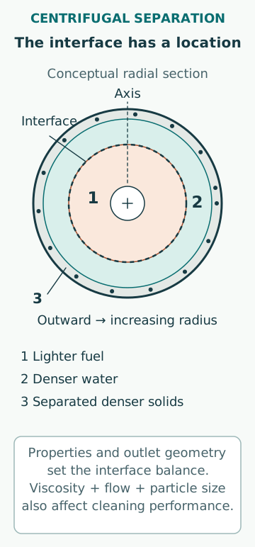
For a conventional two-liquid arrangement, the interface location follows the rotating liquid pressure balance and outlet geometry. Changed fuel properties can shift that balance. The consequences can include loss of the intended seal, oil discharge through an unintended path or reduced useful separation area. Identify the actual symptom and the design mechanism before naming the remedy. Copying a gravity-disc choice from a different fuel or separator is not a calculation.
Use changed density as a diagnostic hypothesis
Alfa Laval’s density-variation guidance states that a gravity-disc setting depends on using the appropriate disc for the conditions. This is a bounded manufacturer statement, not evidence that one adjustment will cure every cleaning problem. A fuel change can alter several properties at once, so the investigation must distinguish interface effects from viscosity, flow, water ingress and the state of the disc stack.
Suppose the measured water content of the treated fuel rises after a tank change. Record the actual inlet temperature, density/viscosity information, throughput, water loading and relevant discharge events. Check whether the timing is consistent with the new fuel reaching the bowl. A result measured before that transition cannot demonstrate performance on the new fuel. Include instrument validity and sampling delay in the hypothesis list; the alarm location may be downstream of a mixing or storage volume.
Measure removal with a consistent denominator
For an original concentration example, take matched inlet and outlet samples with 40 mg/kg and 12 mg/kg of the same specified contaminant. If their mass-flow bases are comparable and no dilution or other mass change invalidates the comparison, the concentration-reduction estimate is 1 − 12/40 = 70%. That does not mean 70% of every particle size was removed, and it does not establish that 12 mg/kg meets the engine’s required inlet quality.
If clean oil is mixed into the outlet stream before sampling, the same apparent reduction can arise partly from dilution. If samples represent different feed batches or operating states, the ratio may not describe the separator at all. Record sampling locations, times, analytical method and uncertainty. Performance verification is strongest when the comparison follows the same material stream under stable, documented conditions and the intended quality criterion is explicit.
Close a maintenance finding with functional evidence
A service record should connect the identified cause to restored function. Confirm the relevant flow path, bowl configuration, discharge system, control inputs and operating conditions, then obtain evidence of cleaning performance. Motor current or rotational speed alone cannot establish water or particle removal. Equally, a single favourable sample cannot prove that intermittent discharge or interface disturbances have been eliminated.
The practical interpretation should keep four questions separate: what force separates the contaminant, how much time and area are available, where the phase interface sits and what the outlet evidence actually demonstrates. This framework explains why the same bowl speed can accompany different results, while keeping equipment adjustments and maintenance procedures within the manufacturer’s approved scope.
Sources
- Centrifugal Separator · GEA · Source check date: 2026-10-06
- Design and operation of fuel cleaning systems for diesel engines, 2024 update · CIMAC Working Group 7 · Source check date: 2026-10-06
- Fuel cleaning · Alfa Laval · Source check date: 2026-10-06
- Avoid losing separation performance when fuel density changes · Alfa Laval · Source check date: 2026-10-06