Knowledge / Machinery and energy
Centrifugal-pump priming: gas pockets, air evacuation and suction establishment
Distinguish priming from liquid-filled NPSH checks, follow a self-priming liquid reserve, and estimate how suction-line gas inventory and air leakage change evacuation demand.
On this page
A motor can turn at its correct speed while a centrifugal pump delivers almost no liquid. One possible reason is that the impeller and suction path contain gas instead of a continuous liquid supply. Establishing that supply is the priming problem. It must be solved before a normal liquid-filled pump curve or NPSH calculation can describe the intended duty.
An air-filled casing is a different hydraulic state
The impeller transfers energy to whatever occupies its passages. Gas has far lower density than water, so a comparable specific-energy rise corresponds to a much smaller pressure rise. Gas also expands as pressure falls. The rotating air in an ordinary centrifugal pump therefore does not usually establish the pressure difference needed to lift a remote liquid column into the casing.
KSB distinguishes ordinary centrifugal pumps from arrangements with a self-priming stage or separation chamber. This distinction is about gas handling during establishment of suction. It does not mean every pump called self-priming can start with all internal chambers completely dry, or that it can tolerate indefinite gas-only operation.
Identify where the air must go
An elevated suction line can contain a substantial initial air inventory. Local high points, an unfavourable reducer orientation or an incompletely vented casing can retain a gas pocket even after liquid reaches another part of the system. A viable priming arrangement needs both a route for liquid to advance and a route for displaced gas to leave. A blocked gas discharge path can defeat an otherwise working evacuator.
An external vacuum device, a designed ejector arrangement, gravity filling under positive suction head or an internal self-priming circuit are different solutions. Their valve states and startup sequence depend on the equipment. The useful general question is not simply whether a motor is running, but whether air is being removed from every volume that prevents continuous liquid flow.
The liquid reserve makes a self-priming cycle possible
In a separation-chamber design, retained liquid mixes with incoming air, the impeller transports the mixture to a separation region, gas leaves, and liquid returns to repeat the process. Removing gas allows the source pressure to advance liquid through the suction line. Once primed, the pump changes to its normal predominantly liquid duty. Other self-priming designs use different internal mechanisms.
KSB’s priming entry explicitly retains the need to fill the self-priming device with liquid before startup. A reserve lost through a leak, drainage or an unsuitable arrangement may remove the very mechanism needed to re-prime. “Self-priming” describes a designed capability under specified conditions, not an exemption from an initial liquid charge or the manufacturer’s operating limits.
Worked example: count the initial gas inventory
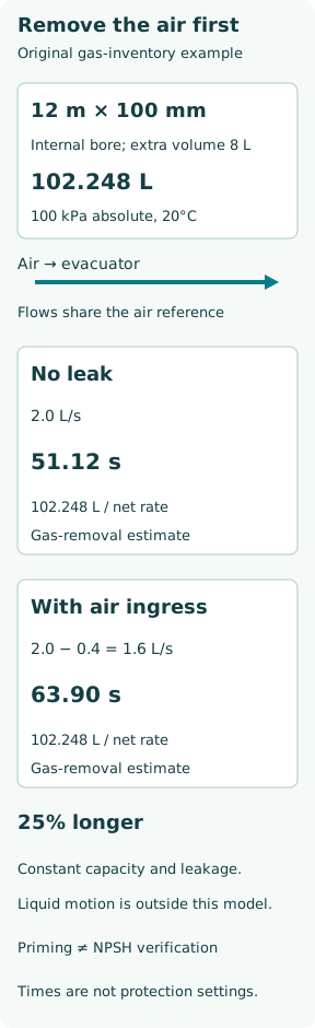
Assume a dry suction pipe with internal diameter 0.100 m and length 12 m. Additional gas-containing casing and fittings contribute 0.008 m³. Initially the air is at a declared reference of 100 kPa absolute and 20°C, with ideal-gas behaviour. The pipe volume is π × 0.100² × 12 / 4 = 0.094248 m³; total initial gas volume is 0.102248 m³, or 102.248 reference litres.
Assume an evacuator removes 0.002 m³/s expressed as free air at that same reference. This is an invented constant mass-equivalent capacity, not actual volumetric flow at its low-pressure inlet. If all the original gas must leave and no additional gas enters, its inventory time is 0.102248/0.002 = 51.12 s. This is a deliberately simplified gas-removal estimate, not a complete prediction of when the pump becomes ready.
A small air leak consumes useful evacuation capacity
Now assume a leak adds 0.0004 m³/s of air on the same pressure/temperature reference throughout evacuation. Net removal is 0.002 − 0.0004 = 0.0016 m³/s. The inventory time becomes 0.102248/0.0016 = 63.90 s, 25% longer than the no-leak case. If ingress equals the available removal capacity at the operating pressure, this simple model has no finite clearing time.
The common reference matters. Subtracting actual suction-volume flow from an atmospheric-reference leak rate would mix different gas densities. Real evacuation capacity and leakage both vary with pressure; dissolved-gas release and vapour may add another load. A time-resolved model would integrate the net mass removal while tracking the changing gas volume and pressure as liquid advances. The two numbers here are screening estimates, not a timeout setting.
Static lift sets a pressure requirement, not the priming time
For a separate hydrostatic illustration, let the liquid surface be 3.0 m below the pump, source pressure 100 kPa absolute and water density 998 kg/m³. Neglect acceleration and friction. The required pressure difference is ρgz = 998 × 9.81 × 3 = 29.371 kPa, leaving about 70.629 kPa absolute at the top of a static continuous liquid column.
This does not certify that a selected evacuator can maintain that pressure while handling the gas load, or that a real liquid column will arrive in 51.12 s. During filling, inertia, changing geometry and losses matter. After liquid flow is established, the available NPSH must be assessed at the actual duty with liquid vapour pressure and line losses. A successful prime and adequate running NPSH are separate requirements.
Air entry can occur without visible liquid leakage
When the suction side is below atmospheric pressure, an imperfect joint can draw air inward rather than leak water outward. Xylem identifies suction-line airtightness and installation faults among priming failure causes. An inlet that intermittently uncovers or draws a vortex can also introduce gas even if every joint is tight. The location and operating condition of the gas source matter.
Loss of prime after shutdown suggests a different time history from failure to clear an initially dry line. Compare liquid-reserve retention, source level, gas-discharge path, evacuator performance and the evidence of leakage. A vacuum indication alone is ambiguous: it may show that a gas space is evacuated while another pocket remains isolated. Conversely, weak vacuum may reflect excessive ingress rather than a defective main impeller.
Protect the pump while verifying the transition
Grundfos notes that dry operation can damage bearings and shaft seals. The permissible priming period depends on the model, fluid temperature, seal arrangement and available liquid reserve. Repeatedly restarting a pump that has failed to prime can accumulate heat without resolving the cause. Do not infer an allowable dry-running time from this example’s inventory calculation.
A credible transition to liquid duty uses the installation’s approved indications: actual delivery, stable appropriate pressures, liquid-presence or level signals where fitted, and correct disengagement of the priming device. A brief splash at one vent does not prove every important gas pocket has cleared. Use the equipment-specific procedure for hazardous, hot or pressurized liquids rather than opening a generic vent described by a diagram.
Separate readiness evidence from a normal-duty calculation
A priming assessment records the initial fill state, suction geometry and volume, source level and pressure, retained liquid, gas evacuation route, capacity reference and leakage assumptions. It then checks the time-dependent transition and the main pump’s permissible startup envelope. Only after liquid continuity is established should a conventional running-duty calculation be treated as representative.
The key balances are simple but distinct: gas must leave faster than it enters; the priming arrangement must produce the required pressure difference; and the liquid-filled pump must subsequently operate within its own hydraulic and thermal limits. A good NPSH figure cannot compensate for an impeller still occupied by gas.