Knowledge / Machinery and energy
Condenser vacuum: non-condensable gases and heat-transfer performance
Separate steam partial pressure, air accumulation, cooling-water duty and removal-system capacity when interpreting a condenser’s absolute-pressure trend.
On this page
A steam condenser can show deteriorating vacuum for more than one reason. Warmer cooling water, reduced cooling flow, fouled surfaces, air ingress or inadequate removal of non-condensable gases can all affect the observed pressure. The useful question is not simply whether a vacuum pump is running. It is which mass-transfer or heat-transfer condition changed and whether the available measurements distinguish those causes.
Start with heat removal and the pressure reference
The NRC’s condenser description identifies the transfer of heat from condensing steam to a circulating cooling-water system. In a surface condenser, the two streams are separated by a heat-transfer boundary. The steam’s phase change, cooling conditions and gas inventory jointly determine the operating state. A device that removes air supports that state; it does not replace the heat sink needed for sustained condensation.
Describe pressure in absolute units when using steam properties. If the local atmosphere is 101.3 kPa and the condenser is at 8.0 kPa absolute, the gauge pressure is −93.3 kPa. A vacuum indication defined against another atmospheric reference would have a different numerical value for the same absolute pressure. Retaining that reference avoids mistaking weather or instrument conventions for a thermodynamic change.
Separate total pressure from steam partial pressure
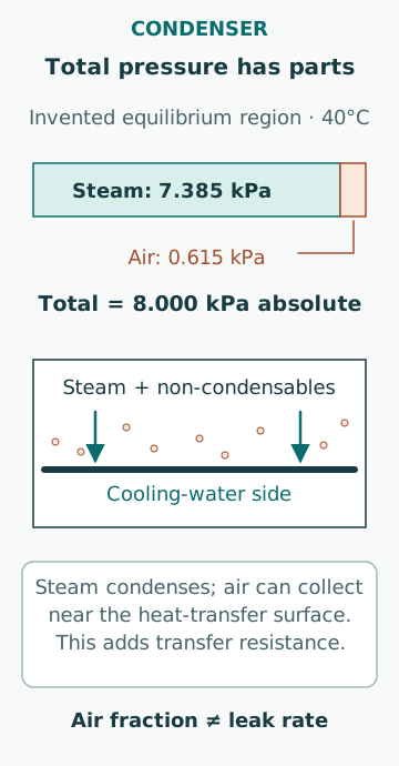
Spirax Sarco’s air-venting explanation applies the sum of partial pressures to steam–air mixtures and explains why the total pressure does not directly supply the steam saturation temperature when air is present. Under an ideal-mixture approximation, Ptotal = Psteam + Pnoncondensable. A steam table applies to the water-vapour component under the relevant equilibrium assumptions, not automatically to the total mixture pressure.
This distinction also limits diagnosis from a pressure and temperature pair. Temperature must represent the considered gas/liquid equilibrium region; a subcooled condensate outlet or an unrepresentative wall sensor cannot simply be substituted. Pressure losses and spatial composition differences can exist inside the condenser. An inferred air partial pressure is only as defensible as these location and equilibrium assumptions.
Work a bounded pressure–temperature example
The NIST water saturation table gives approximately 7.385 kPa at 40°C. For an invented uniform equilibrium region containing pure water and an ideal steam–air mixture at 40°C, suppose measured total pressure is 8.000 kPa absolute. The implied air partial pressure is 8.000 − 7.385 = 0.615 kPa. Its ideal gas-phase mole fraction is 0.615/8.000 = 0.076875, about 7.69%.
The result is not a liquid dissolved-air fraction or a measured leak rate. It also cannot be applied if the temperature is from a colder hotwell while pressure represents another region. An air fraction at one moment describes inventory composition; a leak rate requires a flow balance over time. A higher inferred fraction can arise from more ingress, less removal or changed steam conditions, so the fraction alone does not locate a defect.
Understand the additional transfer resistance
Non-condensable gas can accumulate near a condensing surface as steam leaves the gas phase, creating an additional heat-and-mass-transfer limitation. NRC’s public summary of NUREG/IA-0147 reports condensation experiments in a vertical tube where air fraction and flow affected heat-transfer behaviour. This supports the physical dependence while also showing why a universal percentage penalty cannot be transferred from one geometry to another.
A useful model must consider gas motion, surface temperature and composition near the interface, not merely the bulk pressure. Deposits on the cooling-water side are another resistance with a different mechanism. Both can reduce apparent performance, but cleaning a water passage does not remove an air leak, and increasing air-removal effort does not remove a solid deposit. The observations should distinguish the proposed cause.
Reconcile the cooling-water duty
For a separate steady teaching example, assume cooling-water flow is 100 kg/s, mean specific heat is 4.00 kJ/(kg·K) and the measured temperature rise is 5.00 K. The water-side heat gain is 2,000 kW. If all that duty came from steam condensation with an assumed latent enthalpy of 2,400 kJ/kg, the corresponding condensation rate would be 0.833 kg/s. The assumptions exclude sensible cooling, other heat inputs and losses.
This calculation is not a condenser rating and does not establish its pressure. It checks whether an observed temperature rise and flow are compatible with the proposed duty. Uncertain seawater flow, a biased temperature difference or heat entering elsewhere can distort the balance. Retain the assumed fluid property and measurement uncertainty, especially when the temperature difference is small relative to sensor error.
Write a separate non-condensable inventory balance
Air accumulation follows a balance between ingress, other sources and removal. As a deliberately simplified example, suppose non-condensable gas enters at 0.0100 mol/s and leaves at 0.00800 mol/s while gas-space volume and temperature remain fixed. In 600 s, inventory increases by 1.20 mol. For 50.0 m³ at 313.15 K, the ideal partial-pressure rise is Δp = ΔnRT/V = 1.20 × 8.314 × 313.15/50.0, about 62.5 Pa or 0.0625 kPa.
This is a separate hypothetical transient, not a continuation of the previous condenser example. It assumes fixed rates, uniform mixing and constant volume and temperature; real removal capacity changes with suction conditions and mixture. The purpose is to distinguish an inventory from a rate. A constant pressure may mean balanced sources and removal, not zero air ingress, while a rising pressure may reflect several simultaneous changes.
Assess the removal system at its actual conditions
The DOE Steam System Survey Guide describes air ingress through low-pressure equipment and identifies steam-jet ejectors and mechanical vacuum pumps as common removal methods. Each has supporting conditions that affect achievable performance. A running indication does not prove the required removal rate at the actual suction pressure, gas composition and temperature.
For an ejector, the applicable motive-fluid condition and downstream arrangement are relevant; for a mechanical pump, its specified operating envelope and support services matter. Compare evidence with the actual manufacturer’s curve and procedure. Avoid substituting a nominal free-air capacity for capacity at condenser suction conditions. A standard-volume flow and an actual suction-volume flow are different representations unless the state conversion is included.
Use trends to separate cooling and gas-side problems
Compare condenser absolute pressure with cooling-water inlet and outlet temperatures, flow, steam load and relevant air-removal observations over the same period. A warmer heat sink changes the temperature difference available for condensation. Reduced flow can raise cooling-water temperature rise. A change in air-removal conditions can affect gas inventory even if the cooling side is unchanged. Several causes may coexist.
A credible comparison uses similar operating states or an explicit correction model. A before/after result taken at different steam loads cannot be attributed entirely to maintenance. Likewise, an apparently improved vacuum after a load reduction does not prove a leak has been repaired. Record which variables changed intentionally and which remained uncontrolled before assigning a mechanism to the trend.
Keep diagnosis separate from proving integrity
A pressure trend, heat balance and removal-system check can narrow an investigation, but they do not by themselves demonstrate tube integrity, eliminate every air path or certify condensate quality. A surface condenser also separates fluids whose mixing may matter to the wider steam plant. Evidence about chemical contamination and evidence about non-condensable ingress answer different questions.
Common mistakes are reading saturation temperature from total mixture pressure, treating subcooled condensate temperature as the gas equilibrium temperature, equating pump operation with removal capacity, and calling every vacuum loss an air leak. A strong conclusion states which measurements support the proposed mechanism, their location and basis, and the remaining uncertainty. Any physical testing or change to equipment follows the approved plant-specific procedure.
Sources
- Condenser glossary · US Nuclear Regulatory Commission · Source check date: 2026-10-06
- Air Venting Theory · Spirax Sarco · Source check date: 2026-10-06
- NISTIR5078 water saturation temperature table · NIST · Source check date: 2026-10-06
- NUREG/IA-0147:Steam condensation with noncondensibles in a vertical tube · US NRC · Source check date: 2026-10-06
- Steam System Survey Guide · US Department of Energy · Source check date: 2026-10-06