Knowledge / Machinery and energy
Marine EGR: oxygen dilution, soot loading and corrosion control
Trace exhaust-gas recirculation through combustion, cooling, cleaning and water handling, using explicit gas-mixture and heat-load examples.
On this page
Exhaust-gas recirculation changes the gas entering an engine’s combustion process. Some exhaust returns through a defined conditioning path and replaces part of the fresh supply. The intended reduction in nitrogen-oxide formation is connected to oxygen availability and thermal behaviour, but the returning stream also brings heat, moisture and contaminants. Understanding EGR therefore requires following both the gas loop and the material removed from it.
Distinguish formation control from downstream conversion
MAN’s public propulsion-principles guide explains that recirculated gas has less oxygen than fresh air and changes the heat capacity and mixing of the combustion region, reducing peak-temperature tendencies associated with NOx formation. This is a different intervention from converting already formed NOx in an SCR reactor. An EGR cooler or cleaning stage supports the recirculation process; it is not itself the whole NOx-control mechanism.
The result depends on the engine’s combustion system, load, fuel and validated control strategy. A lower inlet oxygen fraction does not alone quantify emissions or efficiency. The gas temperature, injected fuel, available air and combustion development remain linked. For that reason, a simple mixture calculation can check an assumption but cannot select an EGR setting or prove an emissions tier.
Define the fraction before comparing recirculation rates
An EGR fraction needs a numerator, denominator and physical basis. A mass fraction, dry molar fraction and volume-flow fraction at unlike temperatures are not automatically equal. Recirculated flow divided by total inlet flow also differs from recirculated flow divided by fresh-air flow. Confusing these definitions can make two identical physical cases appear different or two different cases appear identical.
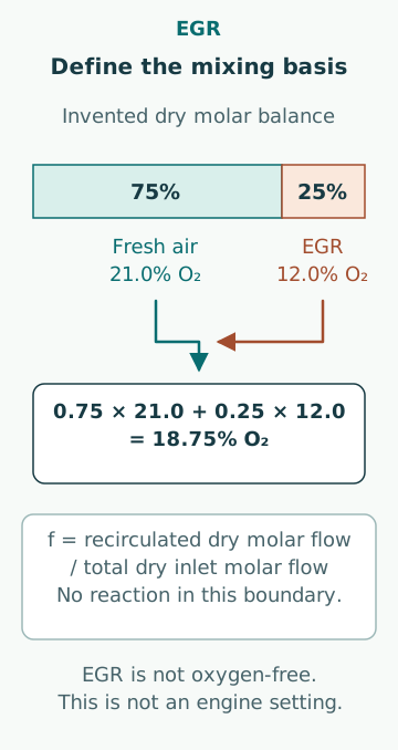
For an original dry-gas example, define f as recirculated dry molar flow divided by total dry inlet molar flow. With f = 0.250, fresh-air oxygen fraction 0.210 and recirculated oxygen fraction 0.120, ideal mixing gives xO₂ = (1 − f)0.210 + f0.120 = 0.1875, or 18.75%. This assumes no reaction in the mixing boundary and consistent dry-gas measurements. It is not an oxygen target for an operating engine.
Use a tracer balance only when its assumptions hold
If a conserved gas species has distinct concentrations in fresh and recirculated streams, it can illustrate the mixture fraction. For a hypothetical dry CO₂ balance, let fresh gas contain 0.040%, recirculated gas 8.000% and the mixed inlet 2.030%. The simple estimate is f = (2.030 − 0.040)/(8.000 − 0.040) = 0.250. This is the same defined dry molar fraction as in the oxygen example.
The inference assumes matched times and bases, representative mixing and no additional source, sink or leakage affecting the tracer. If only the mixed reading were biased upward by 0.200 percentage points, the inferred fraction would become approximately 0.2751. A modest concentration bias thus changes the inferred fraction by about 2.51 percentage points. That is an uncertainty illustration, not a recommended instrument tolerance or a validated onboard estimation method.
Follow the cooling and cleaning path
The public ME-GA EGR description provides an example that includes conditioning, removal of entrained water and a blower in the returning-gas path. The details belong to that engine example. The general assessment asks whether gas reaches the intended destination with the required pressure, temperature and condition, rather than assuming that every EGR system uses the same component order or pressure arrangement.
A cooler removes energy; a separator addresses carried liquid; a cleaning stage transfers selected contaminants from gas to another stream. Those functions should not be collapsed into the word treatment. A machine can circulate gas while one supporting function has degraded. Likewise, a clean-looking outlet does not quantify fine particulate carry-over or prove that the water-removal function is satisfactory.
Calculate the thermal burden with a stated boundary
Take an invented sensible-cooling example: gas mass flow 2.00 kg/s, constant mean specific heat 1.10 kJ/(kg·K) and temperature reduction 120 K. The heat duty is 2.00 × 1.10 × 120 = 264 kW. The formula assumes the specified gas stream and excludes condensation, evaporation, reaction heat and external losses. It is an isolated load estimate, not a cooler rating.
If water condenses, latent energy and the changing stream mass must also be included. Cooling-water inlet temperature and available temperature difference affect actual performance. Comparing two operating days by cooler outlet temperature alone can therefore be misleading when gas flow, inlet temperature or cooling-water conditions differ. Use a consistent mass-and-energy boundary to distinguish a larger imposed load from a loss of heat-transfer capability.
Track contaminant mass rather than appearance
MAN’s public service-experience report records greater sludge and dirt accumulation in scavenge spaces during the described EGR service, with fuel-dependent differences. That is evidence that the material pathway matters; it is not a universal cleaning interval or a prediction for every fuel and engine. The relevant comparison needs the actual contaminant source and the performance of the installed conditioning stages.
For a separate example, suppose a gas stream brings 0.200 kg/h of a specified particulate material to a separator and 90.0% of that mass is captured under the stated conditions. The remaining flow is 0.0200 kg/h, or 20.0 g/h; over 100 h at unchanged conditions it totals 2.00 kg. This is throughput, not necessarily deposited mass. Some may leave by other paths, so accumulation requires an additional balance and evidence about where particles are retained.
Keep water chemistry and material compatibility visible
The historical MAN water-handling note distinguishes water-handling arrangements according to fuel and system conditions. Such distinctions matter because a recirculating cleaning liquid can accumulate what it removes from the gas. Gas cleaning does not erase the captured material; the liquid circuit needs its own inventory, quality control and handling boundary. The published arrangement is an example rather than a universal piping plan.
Corrosion assessment must consider the actual gas and liquid chemistry, temperature, wetted materials and time in service. A single pH value does not describe dissolved salts, suspended solids, local deposits or every corrosion mechanism. Likewise, an acceptable bulk sample cannot rule out a local stagnant pocket. Interpret chemistry trends with sample location and treatment history, and use the specified equipment limits rather than extrapolating a generic pH target.
Separate process-water condition from discharge permission
MEPC.307(73) addresses EGR bleed-off water and distinguishes conditions associated with fuel sulphur and the applicable discharge route. It also addresses onboard documentation and records. A statement that water is suitable for continued circulation is therefore different from a statement that it may be discharged. The applicable Administration requirements, local restrictions and actual approved arrangement must be established.
An oil-content indication alone cannot be detached from all the other applicable conditions and treated as a universal discharge permission. Retaining water onboard also does not remove the need to control tank inventory and subsequent handling. This article does not reproduce a discharge checklist or authorize a release; it identifies the regulatory and physical boundary that an EGR performance discussion must retain.
Use paired observations to distinguish failure mechanisms
A coherent diagnostic record includes engine load and fuel, defined recirculation basis, gas composition, pressures and temperatures at named locations, cooling-water condition, separator performance, liquid chemistry and recorded operating changes. If oxygen changes while the inferred tracer fraction does not, first check measurement bases and timing. If pressure loss rises, compare gas flow and density before attributing it to fouling.
Common errors are describing EGR as simply adding oxygen-free gas, treating a valve command as a measured recirculation fraction, ignoring water and solids transferred out of the gas, and copying another engine’s settings. The useful conclusion names the mechanism supported by the data and the evidence still missing. It preserves the connection between emissions performance, machinery condition and the approved operating envelope.
Sources
- Basic principles of ship propulsion · MAN Energy Solutions · Source check date: 2026-10-06
- EGR offered for dual-fuel ME-GA engine · MAN Energy Solutions · Source check date: 2026-10-06
- Service experience:Emission technologies · MAN Energy Solutions · Source check date: 2026-10-06
- EGR water handling system,Market Update Note MUN2018-12-22 · MAN Energy Solutions · Source check date: 2026-10-06
- MEPC.307(73):2018 Guidelines for EGR bleed-off water · IMO · Source check date: 2026-10-06