Knowledge / Machinery and energy
Onboard carbon capture: solvent regeneration and net emissions balance
Connect absorber capture to regeneration heat, electrical demand and CO2 storage, then calculate why gross capture differs from net emission reduction.
On this page
Capturing 80% of CO2 from a treated exhaust stream does not automatically reduce a vessel’s total CO2 emissions by 80%. Heat and electricity are needed to regenerate solvent and condition the captured gas, and producing those utilities may burn additional fuel. Some exhaust streams may bypass capture. A defensible result therefore starts with the whole comparison boundary, not the absorber percentage alone.
Follow both the solvent loop and the carbon stream
In a representative amine process, conditioned exhaust contacts lean solvent in an absorber. CO2 transfers into the liquid, producing rich solvent. Regeneration releases a concentrated CO2 stream and returns lean solvent for reuse. Captured gas then needs the specified drying, compression and cooling before storage. “Lean” and “rich” describe CO2 loading, not whether the solvent is clean or permanently consumed.
Wärtsilä describes pre-conditioning, absorption, desorption, liquefaction and storage as separate stages. Each has its own utility and operating requirements. The absorber outlet alone cannot prove successful long-term storage or offloading, and solvent reuse does not eliminate makeup, degradation or waste handling.
Why regeneration needs heat
A regeneration heat duty can include reversing CO2 binding, heating the circulating solution and generating stripping vapour. Heat recovery between rich and lean streams reduces part of the sensible duty, but does not make the process energy-free. The achievable cyclic loading also affects circulation: a small difference between rich and lean loading requires more solution to move the same CO2 mass.
DOE’s solvent-pilot description explains lower-temperature absorption followed by heated stripping. It supports the process principle, not a universal marine heat demand. Solvent formulation, pressure, exhaust CO2 concentration, heat integration and capture target change the actual duty. For example, an assumed cyclic capacity of 0.05 kg CO2/kg solution would require 160 t/h of solution to carry 8 t/h CO2; that is a separate liquid-circulation quantity.
Available waste heat needs a temperature and an opportunity cost
A quantity of waste heat is useful only if it is available at a temperature and transfer rate suitable for the capture process. Exhaust heat may already support steam consumers, fuel heating or power generation. Diverting it can create another fuel demand elsewhere. Low engine load can simultaneously reduce heat availability and alter exhaust conditions.
DNV treats energy integration and the storage/offloading chain as central onboard-capture considerations. A whole-vessel comparison should keep service output comparable: equal speed or transport task and comparable hotel/cargo services. Otherwise an apparent capture benefit may partly reflect a different vessel duty.
Worked example: state the boundary before calculating
Assume a vessel’s baseline exhaust produces 10.0 t CO2/h. In the capture case, an absorber removes 80% of that stream, or 8.0 t/h. For this invented steady example, all additional boiler and generator exhaust bypasses the absorber. The original engine duty remains unchanged. This boundary avoids silently crediting capture of the energy penalty.
Assume regeneration duty is 3.0 GJ per tonne CO2 captured and available, uncommitted waste heat is 10 GJ/h. Total regeneration duty is 8 × 3 = 24 GJ/h, equivalent to 6.667 MW of heat. The remaining 14 GJ/h must be supplied separately. These are teaching inputs, not a performance claim for a commercial solvent or vessel.
Calculate additional fuel for heat and electricity separately
Let the auxiliary boiler have 85% efficiency and the additional fuel lower heating value be 42.7 MJ/kg = 0.0427 GJ/kg. Fuel for the extra heat is 14/(0.85 × 0.0427) = 385.73 kg/h. Boiler output heat and fuel input energy are different quantities; omitting efficiency understates the fuel penalty.
Assume electrical demand for capture, compression, drying and cooling totals 0.20 MWh/t captured. At 8 t/h this is 1.60 MW. With a hypothetical 40% generating efficiency, the extra fuel is (1.60 × 3.6)/(0.40 × 0.0427) = 337.24 kg/h. Here 3.6 converts MWh to GJ. Total extra fuel is 722.96 kg/h.
Use an assumed combustion factor of 3.114 kg CO2/kg additional fuel. Extra CO2 is 722.9646 × 3.114/1, 000 = 2.25131 t/h. That factor is a stipulated property of this example’s fuel, not a value for every marine fuel. Upstream fuel emissions and non-CO2 greenhouse gases are excluded from this first boundary.
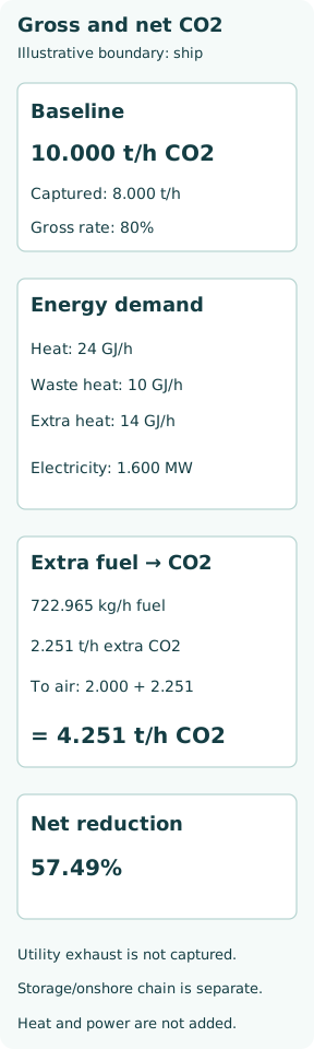
Gross 80% capture becomes 57.49% in the ship balance
The baseline stream releases 10 − 8 = 2.0 t/h after capture. Adding uncaptured utility emissions gives 2.0 + 2.25131 = 4.25131 t/h to air. Relative to the original 10 t/h, net ship CO2 reduction is (10 − 4.25131)/10 = 57.49%. No contradiction exists: 80% and 57.49% refer to different boundaries.
If auxiliary exhaust is also routed into the absorber, the calculation must be solved again. Capturing the extra CO2 increases capture throughput and can require more heat and electricity. Symbolically, captured mass C may satisfy C = η[G0 + Gaux(C)], where G0 is baseline generation and Gaux depends on capture duty. Simply subtracting 80% of the earlier penalty without updating utilities is inconsistent.
Storage and downstream handling affect the retained benefit
At 8 t/h gross capture, an assumed usable CO2 storage mass of 200 t provides 25 h before that capacity is filled, if no offloading occurs. Usable mass is not gross tank volume: permitted filling, thermodynamic state, pressure management and reserve must be established for the actual system. When storage or offloading is unavailable, achievable voyage capture can be lower than the absorber’s running capacity.
For a separately expanded illustrative boundary, assume 98% of captured CO2 is ultimately retained and downstream handling emits 0.15 t CO2/h. Retained capture is 7.84 t/h. Net accounted emission becomes 10 + 2.25131 − 7.84 + 0.15 = 4.56131 t/h, a 54.39% reduction. These extra assumptions are not measured loss rates. This remains a bounded CO2 account, not a complete life-cycle greenhouse-gas assessment.
Capture fraction is not the only operational constraint
Solvent condition, exhaust contaminants, cooling-water availability, heat-exchanger approach temperatures, compressor turndown and tank state can constrain operation. Absorber pressure loss must remain compatible with the engine. Amine handling, pressurized or cold CO2, ventilation and asphyxiation hazards require their engineered safeguards and approved procedures.
A short demonstration at steady load does not establish performance throughout a voyage. Record startup, shutdown, bypass periods, changing load and offloading intervals. A useful average is total retained CO2 and total additional utility consumption over a clearly defined period, rather than an arithmetic average of favourable instantaneous capture percentages.
Report the boundary so another engineer can reproduce it
Retain baseline service, treated and bypassed streams, captured CO2 mass, solvent duty, useful waste heat, extra fuel/electricity, storage availability and downstream assumptions. Separate measurement from estimates. Explain whether the reported result is absorber capture, ship CO2 reduction or a wider retained-carbon balance.
IMO’s current LCA index includes an ongoing regulatory work plan for onboard capture. Technical capture is not by itself proof of eligibility for every emissions-credit or compliance claim. The decisive engineering lesson is simpler: follow carbon to its destination and follow every required energy input back to its source. Net reduction is the balance that remains after both paths are accounted for.