Knowledge / Machinery and energy
Marine SCR: temperature windows, reagent dosing and deposits
Understand SCR reaction stoichiometry, temperature constraints, ammonia slip and deposit mechanisms, with explicit reagent and measurement-basis examples.
On this page
Selective catalytic reduction links an engine’s exhaust to a chemical conversion process. The reactor needs the appropriate reducing agent, a suitable temperature and sufficient contact between gas and catalyst. Increasing a dosing command cannot compensate for every failure of those conditions. A useful assessment therefore follows the chemical demand, distribution of reagent, catalyst condition and downstream consequences together, while keeping the approved engine-system configuration in view.
Follow the reagent through both reaction stages
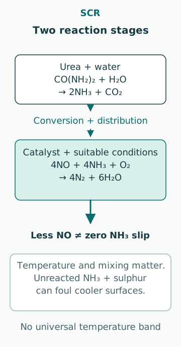
The public MAN 32/40 Tier III guide describes urea conversion to ammonia and subsequent catalytic reduction. An idealized overall urea step is CO(NH₂)₂ + H₂O → 2NH₃ + CO₂. For NO-dominant exhaust, a representative SCR reaction is 4NO + 4NH₃ + O₂ → 4N₂ + 6H₂O. These balanced equations explain the molar demand; they do not describe every intermediate reaction or real operating loss.
The aqueous reagent must be delivered, distributed and converted in the relevant flow path. A tank level or pump-running signal only establishes one part of that chain. Poor distribution can leave some channels short of reagent while others receive an excess, even when the total injected mass appears reasonable. Chemical stoichiometry and physical mixing are therefore separate questions.
Work a molar-demand example before using kilograms
Assume an invented NO inlet flow of 1.00 kmol/h and an illustrative target conversion of 80.0%. Treat all considered nitrogen oxide as NO for this calculation. The representative reaction consumes 0.800 kmol/h NH₃, approximately 13.6 kg/h using a rounded molar mass of 17.0 kg/kmol. Ideally, that requires 0.400 kmol/h urea. With urea molar mass 60.06 kg/kmol, the pure-urea amount is 24.024 kg/h.
If the assumed solution is 40.0% urea by mass, the corresponding ideal solution flow is 24.024/0.400 = 60.06 kg/h, about 60.1 kg/h. These figures are reaction bookkeeping, not a dosing setting. They assume complete conversion and availability of reagent, omit NO₂ chemistry and losses, and do not establish an acceptable slip. Real control follows the validated equipment model and approved operating conditions.
Do not confuse NO mass with NOx reported as NO₂ equivalent
The preceding 1.00 kmol/h NO would have an actual NO mass of approximately 30.0 kg/h using a rounded molar mass of 30.0 kg/kmol. The same number of moles reported on an NO₂-equivalent mass basis would be approximately 46.0 kg/h. That reporting conversion changes the mass number without changing the number of nitrogen-oxide molecules used in the simple example.
An unexplained value labelled kg NOx/h is therefore insufficient for reagent arithmetic. Confirm the reporting basis and the NO/NO₂ composition, together with whether a measurement is dry or wet and how oxygen correction is applied. A mass number copied from an emissions report cannot be inserted as pure-NO mass merely because the chemical example uses NO. This is a common route to a plausible but incorrect reagent estimate.
Understand the temperature window as equipment-specific
Wärtsilä’s public marine-solutions discussion describes both upper and lower temperature constraints and the influence of sulphur on the lower-temperature problem. The useful operating range depends on catalyst, fuel, exhaust composition and installation. A temperature band quoted for one older product is not a universal marine-SCR band. The actual validated range belongs to the approved equipment and its documented operating modes.
Gas temperature at one point is also not the temperature of every catalyst surface. During a load change, hardware thermal inertia, local flow distribution and heat losses can create differences. A reactor with an apparently adequate outlet temperature can still have an unresolved distribution or transient problem. Interpret temperature together with operating history, measurement location and the catalyst model, rather than treating one thermocouple as a complete chemical-state measurement.
Separate conversion efficiency from ammonia slip
Wärtsilä’s ammonia-slip definition refers to unreacted ammonia leaving control equipment. A high NOx reduction can coexist with an undesirable reagent remainder. Conversely, poor NOx reduction does not always mean too little total reagent: the cause may involve temperature, mixing, catalyst activity or an incorrect measurement basis. Increasing supply without diagnosing the mechanism can worsen another part of the result.
For a simple matched-measurement example, inlet 650 ppm and outlet 130 ppm give a concentration reduction of (650 − 130)/650 = 80.0%. The two readings must represent comparable operation and the same gas basis. This ratio does not quantify ammonia slip, mass emissions per hour or specific emissions per kWh. Each of those quantities needs its own measurement or denominator.
Track deposits through the wider exhaust system
The MAN project-guide discussion of SCR influence on boilers explains that ammonia slip combined with sulphur can lead to ammonium-bisulfate deposits on cooler downstream boiler surfaces. Its amount depends on fuel and slip conditions. This mechanism differs from simply accumulating dry soot in catalyst passages, so identifying a deposit only by colour or location is inadequate.
A pressure-loss increase may indicate restricted flow, but comparison requires the exhaust flow, density and measurement points to be comparable. A higher flow can raise pressure drop without any new deposit. Chemical analysis, operating history and equipment inspection may be needed to distinguish soot, ash, reagent-related material and other causes. The appropriate maintenance method is equipment-specific; a diagnosis of deposits is not permission to apply an improvised cleaning process.
Use space velocity without inventing a residence time
The 2025 IMO SCR guidelines define space velocity from a specified reference gas volume flow divided by catalyst-block volume. In an original arithmetic example, 20,000 m³/h referenced to 0°C and 101.3 kPa, as defined by the guidelines, divided by 4.00 m³ of catalyst-block volume based on the outer dimensions is 5,000 h⁻¹. Doubling that referenced flow with unchanged block volume doubles the ratio to 10,000 h⁻¹.
The reciprocal of this parameter is not automatically the physical residence time through the catalyst’s open channels. Actual hot-gas volume, void fraction, geometry and distribution matter. Keep the reference temperature and pressure attached to a quoted volume flow. A standard cubic metre and a cubic metre at reactor conditions contain different amounts of gas unless their state is the same.
Read the approved system boundary and current guidance
IMO adopted MEPC.399(83) in April 2025 and identifies it as superseding the 2017 SCR guidelines. Its implementation invitation distinguishes ship-construction and SCR-delivery dates; determine the actual applicable basis instead of assuming that one publication year covers every installation. The guidance treats the engine, SCR chamber, injection and relevant performance controls as a system.
The Technical File and verification arrangements connect hardware, reagent, control and evidence. A replacement catalyst or altered reagent concentration can affect that relationship even if the reactor casing remains unchanged. An isolated efficiency calculation cannot establish continued certification. Assessment should use the applicable approved documentation and retain the evidence supporting any maintenance or configuration change.
Choose observations that distinguish the competing causes
The public NOx-reducer system description includes dosing, injection/mixing, temperature and differential-pressure monitoring as distinct functions. For an unexplained performance change, assemble engine load, fuel properties, temperatures, reagent quality and consumption, comparable inlet/outlet NOx, relevant slip evidence and pressure loss. Their combined pattern is more informative than a dosing command alone.
Common mistakes are treating urea solution mass as pure-urea mass, mixing NO and NO₂-equivalent units, assuming more reagent always improves the result, calling every pressure rise fouling, and interpreting one concentration ratio as regulatory compliance. A sound explanation states which mechanism fits the observations and which competing mechanisms remain unresolved. That makes the next verification useful without turning a teaching calculation into an operating prescription.
Sources
- MAN 32/40CD TCF turbocharger variant IMO Tier III, Project Guide – Marine, 2025-06-16 / 1.0 · MAN Energy Solutions · Source check date: 2026-10-06
- Wärtsilä Solutions: Marine/Oil&Gas Markets,2016 · Wärtsilä · Source check date: 2026-10-06
- Ammonia slip · Wärtsilä · Source check date: 2026-10-06
- Project Guide PG7020-0145,2024-05-24 · MAN Energy Solutions · Source check date: 2026-10-06
- MEPC.399(83):2025 Guidelines on SCR Systems · IMO · Source check date: 2026-10-06
- NOx Reducer System · Wärtsilä · Source check date: 2026-10-06