Knowledge / Machinery and energy
Shaft generators: power flow in PTO, PTI and take-home modes
Account for mechanical and electrical power in both directions, include conversion losses, and calculate the power genuinely left for take-home propulsion.
On this page
“Shaft generator” names a machine by one of its jobs. In a suitable installation the same electrical machine can also be a motor. PTO takes mechanical power from the propulsion train to feed the ship’s electrical system; PTI sends electrical power into the shaft to assist propulsion; take-home operation uses an available electrical source to propel the vessel when the main engine is unavailable. The names become useful only when the direction of power, equipment limits and surviving support systems are made explicit.
Start with the shaft and bus boundaries
Draw a common mechanical reference plane and the electrical bus feeding or receiving the converter. State whether gearbox, transformer, shaft-bearing and cable losses are inside or outside the account. Otherwise two perfectly reasonable kW figures can describe different points in the same power path. In the examples here, a directly coupled machine is used, gearing and other mechanical transmission losses are neglected, and all figures are steady active power.
ABB describes PTO, PTI and PTH as distinct operating modes of its shaft-generator package. That does not mean every installed generator supports all three. Converter topology, excitation, cooling, protection, mechanical connections and control functions determine which modes are actually available. A one-way electrical power path cannot be made bidirectional merely by selecting a different screen label.
PTO: electrical demand adds mechanical load
In PTO, the main engine supplies propeller power plus the mechanical power extracted for electrical generation and the included losses. If ηm is machine efficiency and ηc converter efficiency, Pbus = Pshaft,extracted ηm ηc. To supply a specified bus demand, divide by the efficiencies: Pshaft,extracted = Pbus/(ηm ηc). Multiplying the bus demand by efficiency would incorrectly make the required input smaller than its output.
A new electrical load can therefore push the main engine toward a torque or power limit even when the propeller command is unchanged. The control system may need to reduce another load, start another source or limit generation according to its approved strategy. Conversely, suddenly losing a large electrical load changes shaft loading. Mechanical generation and ship electrical power management belong to one coupled energy system.
PTI: power reverses, losses do not disappear
In PTI the bus supplies the converter, the electrical machine produces torque and the shaft receives power. The idealised account becomes Pshaft,added = Pbus,in ηc ηm. The main engine and electric motor contributions can then add at the common shaft plane, provided couplings, shafting and propeller can accept them.
The electrical energy still needs an origin: generator sets, a battery or another authorised source. A shaft generator cannot simultaneously extract and return the same energy to create a net power gain through one conversion loop. The same machine may change roles over time, but each mode must have an explicit energy source and loss path. The distinction is particularly important when a “hybrid boost” figure is compared with available generating capacity.
Why a converter permits variable-speed operation
For a synchronous machine, electrical frequency f = p n/120 when p is the number of poles and n is mechanical revolutions per minute. An illustrative 12-pole generator gives 50 Hz at 500 rpm and 40 Hz at 400 rpm. Without a suitable decoupling arrangement, that frequency change is unsuitable for a bus expected to remain at fixed frequency.
ABB’s variable-frequency-drive guide explains how conversion broadens the usable shaft-speed range. A machine-side converter and bus-side converter can separate machine frequency from bus frequency through their intermediate electrical link. This does not remove low-speed torque, voltage, current or thermal limits. Nor does it automatically establish a dead bus: island operation requires the designed voltage/frequency-forming capability and its supporting supplies.
Worked example: compare PTO and PTI on the same boundary
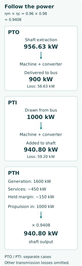
Use hypothetical constant efficiencies ηm = 0.96 and ηc = 0.98, giving ηcombined = 0.9408. These are teaching assumptions, not an ABB or RENK performance claim. In PTO, 900 kW delivered to the bus requires 900/0.9408 = 956.63 kW from the shaft. Conversion losses are 56.63 kW. If the propeller requires 5,000 kW at the same reference plane, the main engine must provide 5,956.63 kW before any omitted transmission losses.
In a separate PTI operating case, 1,000 kW drawn from the bus produces 1,000 × 0.9408 = 940.80 kW on the shaft. If the main engine simultaneously supplies 5,000 kW, the idealised total reaching the propeller plane is 5,940.80 kW. That sum is an energy account, not permission to exceed an engine, coupling, shaft or propeller rating. Efficiencies vary with speed, torque and temperature in a real installation.
Take-home begins with the surviving electrical budget
Suppose the generation that remains available after the defined failure can deliver 1,600 kW at the bus. Essential and other retained service loads require 450 kW. Reserve a further 150 kW of capacity for the assumed operating margin. The propulsion converter may then draw at most 1,600 − 450 − 150 = 1,000 kW under this steady budget. The reserve is unused capacity, not an extra physical consumer.
With the same teaching efficiencies, the available propulsion shaft power is 940.80 kW. It is neither the 1,600 kW generator total nor automatically the motor’s nameplate power. A motor rated above this level remains constrained by the bus budget; one rated below it creates a different constraint. Transient load pickup, motor current, cooling and overload duration require separate checks. The chosen 150 kW reserve is an illustration, not a recommended shipboard reserve rule.
Low speed can be torque-limited before it is power-limited
Mechanical power satisfies P = Tω, with angular speed ω = 2πn/60. Delivering 940.80 kW at 120 rpm requires about 74.87 kN·m. At 60 rpm the same power would require about 149.73 kN·m. A hypothetical continuous torque limit of 80 kN·m would instead permit only 80 × 2π × 60/60 = 502.65 kW at 60 rpm.
Thus “the bus has enough kilowatts” does not prove that the motor can develop the required low-speed power. A geared arrangement changes the torque and speed at each shaft plane and introduces its own limits. In addition, propeller absorption, controllable-pitch capability where fitted and ship resistance determine the attainable operating point. No take-home vessel speed can be calculated from the electrical budget alone.
A failed engine must not become an unexamined load
The physical condition of the failed main engine matters. If it cannot safely rotate, a designed disconnection route may be necessary for electric propulsion. RENK’s KAZ device is one concrete example of a main-machine disconnect used in a PTH architecture. Its MARHY diagrams show different clutch and engine states for PTH and PTI. These are product examples, not instructions to operate a clutch on an unspecified vessel.
The surviving propulsion path must also retain shaft lubrication, bearings, cooling, pitch control if required, control power and steering. A shared cooling or electrical failure can defeat both normal and alternative propulsion. Define the failure being credited and check the resulting configuration; counting two energy sources is not proof of independence. PTH capability is a designed and verified function, not a synonym for having an electric machine on the shaft.
Evaluate the mode transition as well as the final mode
A correct steady-state diagram does not demonstrate a successful transition. The installed sequence must establish the necessary bus and auxiliaries, verify permitted coupling states, control torque changes and coordinate protective functions. Which controller sets voltage and frequency, which sets torque or active power, and which prevents overload must remain unambiguous. These interfaces are verified through the approved commissioning and test programme.
A useful record states the initial mode, initiating event, electrical and mechanical availability, measured power direction, losses or efficiency basis and limiting component. Fuel savings require a further comparison of marginal fuel consumption and the operating profile; a lower conversion loss alone is not a fuel-saving calculation. The simplest durable rule is to follow energy from its source to the propeller or consumers, subtract losses once and check every constraint along the surviving path.