Knowledge / Machinery and energy
Tank venting: pressure, vacuum and changing liquid volume
Use gas-volume, temperature and pressure balances to understand tank breathing, vent restrictions and the distinct evidence needed for pressure and vacuum protection.
On this page
A tank that receives or loses liquid also changes the space available to its gas. Unless gas can move through the intended path, or its inventory changes by another process, pressure changes with that volume. Heating, cooling, evaporation and condensation add further demands. Venting therefore belongs in the same physical description as liquid transfer, even when the transfer pump and liquid line appear to be operating normally.
Define the gas space as a changing control volume
For a rigid tank with a liquid surface, the gas-space volume is the tank volume minus the liquid volume. Liquid entering reduces that space; liquid leaving increases it. At approximately constant pressure and temperature, non-volatile liquid displacement would require a corresponding gas-volume transfer at tank conditions. The word corresponding is important: it is not automatically the same numerical flow when gas is reported at standard conditions.
Name all gas paths, including any common header, return connection, blanketing supply and relief route. Also identify whether the liquid can evolve vapour or absorb gas. A gas balance written only around an apparent vent outlet may miss another connected path. Conversely, the existence of a connection does not establish that it has adequate capacity in the current operating arrangement.
Keep displacement and vapour generation separate
IMO’s historical technical circular on tanker VOC management distinguishes existing cargo-tank vapour displaced during loading from vapour generated during the loading process. The physical distinction remains useful: replacing gas space with liquid is one contribution, while evaporation or gas evolution is another. The circular’s examples are not used here as current design settings or as a universal requirement for every tank.
For an ideal non-volatile liquid entering at 100 m³/h, maintaining unchanged gas pressure and temperature would require approximately 100 m³/h of gas to leave at those same tank conditions. This is a displacement-only balance. It excludes vapour generation, thermal effects, compressibility within the flow path and any design allowance. It cannot be used as a complete vent-sizing calculation.
See the sensitivity of a trapped gas pocket
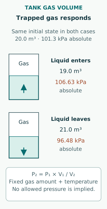
Take an invented fixed amount of ideal gas initially occupying 20.0 m³ at 101.3 kPa absolute. Assume constant temperature, a rigid tank and no vapour generation, condensation or leakage. If liquid entry reduces the gas volume to 19.0 m³, the gas law gives P₂ = 101.3 × 20.0/19.0 = 106.63 kPa absolute. Relative to the unchanged external pressure, that is approximately 5.33 kPa gauge.
If liquid withdrawal instead increases the gas space to 21.0 m³, the same model gives 96.48 kPa absolute, or approximately −4.82 kPa gauge. These are separate hypothetical cases starting from the same initial state. They are not allowable tank pressures or predictions of structural survival. The example illustrates how a small liquid-volume change can matter when the available gas pocket is comparatively small.
Do not turn a transfer rate into a permitted response time
At an assumed constant liquid flow of 100 m³/h, a volume change of 1.00 m³ takes 0.0100 h, or 36.0 s. Combining that arithmetic with the preceding closed-gas model describes an invented transient boundary. It does not establish that an actual tank can tolerate the corresponding pressure or that there are thirty-six seconds available for a response.
Real rates can change as pressure opposes the pump or affects gravity flow. Gas temperature, liquid vapour pressure, structural movement and available leakage paths can also change. A proper transient assessment needs those behaviours and the approved pressure limits. An operator’s normal observation interval must not be justified by a simplified example that omits the mechanism determining damage or protection.
Include thermal breathing and changes of phase
Emerson’s tank-blanketing explanation distinguishes liquid movement from thermal breathing and notes that volatile liquid or flashing changes the gas demand. A stationary liquid level is therefore not proof that vent demand is zero. Cooling of gas or condensation can reduce pressure; heating or evaporation can increase it. The extent depends on the actual contents and energy exchange.
For a separate ideal-gas illustration with fixed gas amount and volume, warming from 293 K to 303 K increases absolute pressure by 303/293 − 1, about 3.41%. Starting from 101.3 kPa absolute, the result is about 104.76 kPa absolute. A real tank containing condensable vapour needs a phase-equilibrium and energy assessment; its response is not captured by this fixed-gas example.
Distinguish opening pressure from delivered flow
HSE’s relief-and-vent-system discussion identifies piping pressure loss, backpressure and shared-system loading as relevant to protection. A valve beginning to open does not mean the complete route can pass every required flow while keeping tank pressure within its design limits. The inlet, device, outlet, common header and destination form one flow path whose interactions must be assessed.
Pressure protection and vacuum protection also act in opposite directions and can have different flow capacities or failure modes. A combined device’s label is not proof that both functions have been demonstrated. For an isolated force illustration, a differential pressure of 5.00 kPa acting uniformly on a 10.0 m² area produces 50.0 kN. That is only a resultant force; shell buckling, supports and local stresses require structural analysis, so it is not a failure-pressure calculation.
Follow where the discharged vapour goes
HSE’s FPSO/FSU cargo-tank venting notice highlights exposure and ignition risks from emitted vapours, including the relevance of low-wind conditions. It also discusses drainage of condensate in vent lines. This is a bounded offshore example showing that pressure relief and safe handling of the released material are separate questions. A functioning outlet does not by itself establish a harmless surrounding atmosphere.
Assess the intended destination, neighbouring openings and the possibility that liquid accumulation changes the gas path. A common header can connect tanks with different conditions, while a return connection can introduce a pressure imposed elsewhere. The relevant arrangement and restrictions depend on tank service and applicable rules. Neither an open connection nor an inerting supply removes the need to understand those interactions.
Treat maintenance as a change to the protective function
A 2021 HSE road-tanker safety alert describes a modified pressure/vacuum valve whose vacuum-relief element became stuck open. HSE considered it likely that the modification had been made during routine servicing. This is not a marine regulatory precedent; it is direct evidence that seemingly convenient mechanical changes can alter a protective device’s movement and containment function. The alert also distinguishes verification of pressure and vacuum functions.
A useful maintenance record establishes the correct device identity, configuration, test scope, installation path and restoration state. Bench evidence may show the device works while leaving an obstructed installed line outside the test. An external visual inspection answers another, narrower question. Keep these boundaries explicit and use the manufacturer’s approved procedures; no adjustment, bypass or improvised vent-opening method follows from the examples here.
Interpret pressure with transfer and configuration history
When a pressure trend changes, compare liquid flow, gas temperature, tank level, gas-supply condition and the actual connected route. Check the pressure reference as well: absolute and gauge pressure are not interchangeable, and external atmospheric pressure can vary. A pressure sensor measures its own connection, which may not represent every tank on a partly isolated header.
Common errors are assuming an empty-looking tank has unlimited gas capacity, equating a relief setpoint with full-flow performance, checking only one direction of a combined valve, and treating no liquid movement as no vent demand. A sound account states the source of the breathing demand, the complete available path and the evidence that each required function remains effective. It keeps normal process operation, protective capacity and vapour exposure within their own stated boundaries.
Sources
- MEPC.1/Circ.680:Technical information on systems/operation to assist VOC management plans · IMO · Source check date: 2026-10-06
- Tank Blanketing Pressure Regulation Calculations · Emerson Automation Experts · Source check date: 2026-10-06
- Relief systems/vent systems · UK HSE · Source check date: 2026-10-06
- Assessment of adequacy of venting arrangements for cargo oil tanks on FPSO/FSU · UK HSE · Source check date: 2026-10-06
- Failure of a road tanker pressure/vacuum relief valve · UK HSE · Source check date: 2026-10-06