Knowledge / Machinery and energy
Thermal-fluid heaters: surface heat flux, film temperature and fluid degradation
Calculate the temperature hidden between the bulk liquid and the heating surface, separate local film heating from whole-heater temperature rise, and interpret degradation evidence.
On this page
A thermal-oil outlet temperature can look normal while fluid close to a heating surface is much hotter. The bulk sensor sees a mixed stream; heat must first cross a local boundary layer. High local heat flux, poor circulation or a deposit can change that temperature path. Understanding the path is essential before assigning a degradation problem to the fluid or simply raising heater output.
Bulk temperature is not the hottest fluid temperature
Bulk temperature represents the main fluid stream at a stated location. In heat-transfer-fluid service, the maximum film temperature means the hottest fluid in contact with the heating surface. This usage is different from the arithmetic mean of wall and bulk temperature sometimes called a film temperature when evaluating properties for a convection correlation.
Eastman explicitly distinguishes bulk and maximum wall-contact film temperatures. A thin fluid volume can experience severe local thermal stress even though the average stream remains below its recommended bulk limit. The sensor location, mixing and response time determine what a displayed temperature actually represents.
Write the local heat-transfer balance with consistent areas
For a clean surface and a single-phase steady approximation, q″ = h(Tw − Tb). Here q″ is heat flux into the fluid in W/m², h the fluid-side convection coefficient in W/(m²·K), Tb local bulk temperature and Tw the fluid-contact surface temperature. Thus Tw = Tb + q″/h. The ratio q″/h is a temperature difference, not an absolute temperature by itself.
Dow defines the film coefficient through convection per unit area and temperature difference. Use the same area basis for flux and coefficient. Heat released by a burner is not automatically the heat transferred into the fluid, and an outside-tube flux cannot be combined with an inside-area coefficient without an area conversion.
Worked example: average duty can hide a local peak
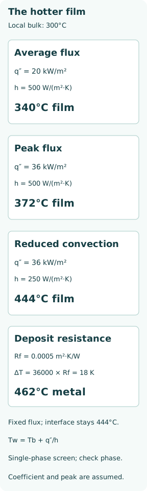
Assume 500 kW actually reaches the fluid through 25 m² of internal heated area. Average flux is 500000/25 = 20000 W/m². At a chosen local bulk temperature of 300°C and h = 500 W/(m²·K), the clean-surface estimate is 300 +20000/500 = 340°C. These are illustrative operating inputs, not a measured heater or a selected fluid’s certified coefficient.
Now stipulate a local peak-flux factor of 1.8, so q″peak = 36000 W/m². At the same local bulk temperature and coefficient, the estimated peak wall-contact fluid temperature becomes 300 +36000/500 = 372°C. Using only the average flux would miss 32 K of local temperature elevation. Fired-heater radiation patterns, geometry and flow distribution must establish the real peak factor.
Reduced convection can exceed a film limit while bulk looks acceptable
For a sensitivity case, hold the local bulk temperature and peak flux fixed but reduce h from 500 to 250 W/(m²·K). The temperature rise doubles from 72 to 144 K, giving a single-phase screening estimate of 444°C. This does not assert that halving pump flow exactly halves h; the coefficient depends on geometry, velocity, viscosity and other properties.
As a specific published reference, Eastman lists Therminol 66 maximum bulk and film temperatures of 345°C and 375°C. The example’s 300°C bulk lies below that bulk number, while 372°C has only 3 K nominal film margin and 444°C exceeds the film number by 69 K. These comparisons do not approve the heater or recommend the product. Uncertain local flux and h can overwhelm a 3 K margin.
Check the phase before trusting the temperature estimate
The preceding equation assumes an appropriate single-phase convection model. Local pressure and fluid vapour pressure must be checked before interpreting a large calculated wall temperature as an actual liquid-film temperature. If boiling, vapour blanketing or major property variation occurs, a different heat-transfer model is required. The high calculated number is a warning that the assumed regime or operating condition may be unacceptable, not proof that liquid actually remains at that temperature.
Thermal stability limits are also different from flash point and autoignition temperature. A fluid can operate in a designed closed system above its flash point while still posing a serious leak/fire hazard. Conversely, staying below a published bulk limit does not make a leak onto hot surfaces harmless. Fluid compatibility, containment and fire protection remain separate design checks.
A deposit adds a temperature drop, with a clear boundary condition
Continue the peak-flux/reduced-h screen and insert a stipulated deposit resistance Rf = 0.0005 m²·K/W between the metal and fluid-contact surface. The deposit temperature drop is q″Rf = 36000 ×0.0005 = 18 K. At the same imposed heat flux and local bulk state, the metal beneath the deposit would be 444 +18 = 462°C in this simple series-resistance model.
The fluid-contact interface remains 444°C in that fixed-flux calculation; the additional 18 K is across the deposit. It would be incorrect to add it indiscriminately to every fluid temperature. If metal temperature or burner input is constrained instead of fluid-side heat flux, transferred duty may fall. Residual fluid within a porous deposit can have a different exposure, which this lumped model does not resolve.
Whole-heater temperature rise is a separate energy balance
For a separate illustrative steady balance, use Q̇ =ṁcp(Tout − Tin), with negligible heat loss and constant assumed cp = 2.5 kJ/(kg·K). For 500 kW, inlet 275°C and flow 8 kg/s, the bulk rise is 500/(8 ×2.5) = 25 K, giving outlet 300°C. At 4 kg/s with the same duty and inlet, the rise becomes 50 K and the outlet 325°C.
This second example shows why reduced circulation can also raise the bulk temperature if duty does not change. It is not the same boundary condition as the previous comparison that deliberately held local Tb at 300°C. A coupled heater calculation must solve both bulk heating and local heat transfer, with actual temperature-dependent enthalpy and flow distribution. A constant cp here is a teaching assumption, not a Therminol property fit.
Distinguish thermal degradation, oxidation and contamination
Excessive thermal exposure can create lower- and higher-boiling degradation products and, under severe conditions, insoluble material or coke. Oxygen exposure introduces a different chemical pathway; contamination can alter properties or produce deposits without the same thermal history. The mechanisms can interact, so colour or one outlet reading is insufficient evidence for a root cause.
Eastman’s in-service analysis includes viscosity, acid number, low/high boilers, insoluble solids and moisture. Interpret trends with sampling location, age, top-up history and the fluid supplier’s limits. Removing solids by filtration does not reverse dissolved chemical degradation, and replacing the fluid without correcting a heater hot spot can recreate the problem.
Protection should follow heat input and verified circulation
A credible assessment links heater duty to proven circulation and the manufacturer’s minimum-flow requirement, then checks startup, shutdown and loss-of-flow events. Pump motor status alone is not proof of flow through every heated passage. Cold-fluid viscosity, bypass arrangements, blocked strainers and maldistribution can all change local heat removal. Residual stored heat also matters after firing stops.
Use the approved heater sequence and fluid-specific handling procedures; the numerical examples are not trip setpoints or instructions to modify interlocks. The useful engineering record contains heat transferred to the fluid, relevant area, local peak flux, coefficient assumptions, bulk/film/metal temperature definitions and fluid-condition evidence. Only then can a normal-looking outlet temperature be interpreted in the context of the hottest surface exposure.