Knowledge / Machinery and energy
Tunnel thrusters: forward speed, recirculation and available lateral force
Why propeller thrust differs from the side force acting on a ship, and how crossflow, recirculation, immersion and the hull alter a tunnel thruster’s contribution.
On this page
A tunnel thruster accelerates water across the vessel, but the force acting on the complete ship is not simply the force measured on its propeller. Pressure changes on the tunnel and surrounding hull also matter. Once the vessel moves ahead, approaches a quay or rises in a wave, the surrounding flow changes. The correct question is therefore how much useful lateral force and yaw moment the installed system delivers in the particular condition.
Choose the force boundary before quoting thrust
Distinguish propeller thrust, force on the installed thruster–hull combination and the net force on the entire vessel after wind, current and other propulsion forces are included. These are three different accounting boundaries. A manufacturer’s component figure or a zero-speed test result is meaningful only when its boundary, power and installation conditions are stated.
Choose positive lateral force in the desired direction. A useful accounting identity is Yinstallation = Ypropeller + Ytunnel + Yhull, where the last two terms include the appropriate pressure and viscous forces on their separate wetted surfaces. Do not count the same surface twice. This identity is not a prediction formula: its individual terms require tests, validated computation or installation-specific data. It explains why an apparently healthy motor and propeller do not prove the intended ship force.
Why forward motion changes the answer
At rest, the thruster draws water toward one opening and discharges a jet from the other. With forward motion, longitudinal flow crosses both openings and bends the transverse jet. This changes the local pressure distribution, jet separation and flow entering the tunnel. The change in useful force can be substantial even though shaft power has not fallen. A fixed percentage loss per knot would conceal these coupled effects.
The relevant velocities are water-relative, not speed over ground alone. A moored or position-keeping vessel can have crossflow because of current; a vessel moving over ground with the water can have a different inflow. Drift angle also changes the relative direction of the flow. MARIN’s TT-series programme explicitly treats ship speed and drift angle as installation-dependent prediction questions. Neither its research scope nor a generic article supplies a universal speed at which every tunnel thruster becomes ineffective.
Inlet suction and outlet recirculation are not the same loss
MARIN’s crabbing study distinguishes favourable inlet-side hull-pressure effects from adverse outlet recirculation. The inlet and outlet cannot be represented by one rule such as “all suction reduces thrust.” Pressure integrated over the actual hull geometry determines its signed contribution.
At the outlet, a jet that remains close to the hull or is redirected into a recirculating region can change the pressure field and reduce the useful force. Recirculation here means that discharged water participates in a returning flow region; it does not necessarily mean that all of the jet travels around the ship and re-enters the opposite opening. Interactions with another thruster or propeller create additional possibilities. The engineering task is to identify the actual flow path, not assign every force loss the same name.
Immersion introduces a different mechanism
Cavitation is local vapour formation when liquid pressure becomes sufficiently low. Ventilation is ingestion of air or gas from outside the liquid stream. A tunnel near the free surface can draw air during heave, pitch or changing local water level. These mechanisms can both reduce performance, but they require different evidence. Noise alone does not distinguish them.
MARINTEK’s forced-heave tunnel tests measured both propeller and whole-model loads and investigated loss and recovery during ventilation. That distinction matters in waves: a time-averaged force may hide brief periods with little available thrust. Mean draught alone is insufficient; local immersion at the tunnel, wave elevation, vessel motion, loading and tunnel geometry must be considered together. A single minimum-submergence rule cannot be transferred between installations without its design basis.
Worked example: a signed force budget
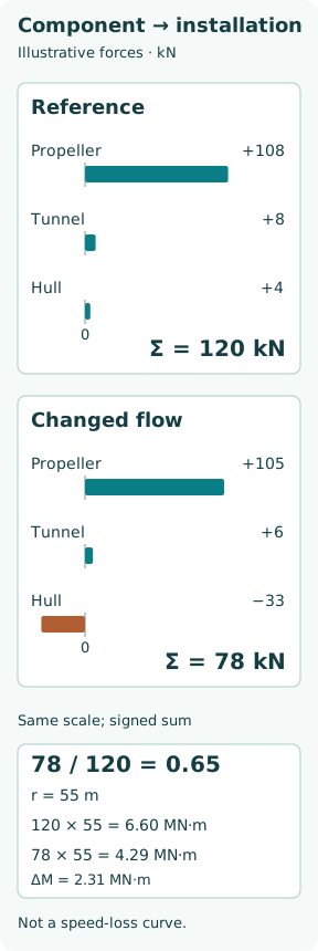
Use invented force components to illustrate the accounting. In a reference zero-speed condition, let the propeller contribute +108 kN, tunnel surfaces +8 kN and surrounding hull +4 kN. The installed side force is 120 kN. In a second operating condition, suppose the corresponding values are +105, +6 and −33 kN. The installed contribution becomes 78 kN. These values are assumed teaching inputs, not measured data or an empirical relation to a stated ship speed.
The ratio is 78/120 = 0.65. The propeller force decreased by only 3 kN, whereas the complete installation lost 42 kN of useful force. Most of that difference lies in the assumed surrounding-hull contribution. This is why component thrust cannot simply be substituted for installed side force.
If the resultant force acts 55 m forward of the vessel’s centre of gravity, and its effective application point is assumed unchanged, the reference yaw moment magnitude is 120 × 55 = 6,600 kN·m = 6.60 MN·m. The second condition provides 78 × 55 = 4,290 kN·m = 4.29 MN·m, a reduction of 2.31 MN·m. Actual distributed pressures can also shift the resultant’s application point; the fixed lever arm is a teaching simplification.
Side force and yaw control must be checked together
Continue the example with an opposing environmental side force of 90 kN. The thruster’s 78 kN leaves −12 kN in the chosen lateral direction before other contributions. That force balance says nothing by itself about yaw balance, because the wind/current resultant may have another lever arm. A bow thruster can produce a useful turning moment while still being unable to translate the ship sideways against the environment.
For several devices, sum both lateral forces and moments about one common reference. Use the actual force directions and locations; do not add nameplate kilowatts as though they were kilonewtons. If thrusters interact, summing their isolated force curves can overstate the combined result. Allocation logic needs the operating limits and interaction evidence that apply to the particular configuration.
The quay, seabed and tunnel openings belong in the model
A nearby wall restricts where water can enter and leave; shallow water also changes the available flow space. The MARIN study found that quay-related hydrodynamic forces can assist or oppose a manoeuvre depending on motion direction. It is therefore unsound to apply one favourable harbour-test result to both departure and approach, or to a different under-keel clearance.
Opening shape, grids, tunnel length and adjacent hull curvature influence losses and pressure recovery. A scale model must represent more than the nominal tunnel diameter: relatively thick model grid bars and different viscous behaviour can change the extrapolation. A modification intended to reduce transit drag may also alter manoeuvring force. Its effect should be evaluated over the intended operating profile instead of being judged only by appearance or motor current.
Power availability and hydrodynamic availability are separate
Even with a favourable flow field, the drive must remain within its electrical, thermal and mechanical limits. Short harbour duty and sustained station-keeping duty are not interchangeable. Wärtsilä distinguishes auxiliary-use and DP-use ratings for its transverse thrusters. A nominal maximum power is not evidence that this power is continuously available under every cooling or generator configuration.
For a fixed geometry and similar inflow, the familiar approximate relationships thrust ∝ speed squared and power ∝ speed cubed can help interpret a trend. Their coefficients are not constant across ventilation, strong crossflow or changing pitch. Increasing revolutions cannot be assumed to recover installed force in direct proportion, and can encounter current, cavitation or thermal limits before the manoeuvring deficit is removed.
What evidence makes a capability claim credible?
Record power or shaft torque and speed, pitch where applicable, water-relative flow, draught and trim, tunnel immersion, water depth, quay clearance, other operating propulsors and the force/moment measurement boundary. State whether results are steady, peak, mean or a time history. Include measurement uncertainty and the model-to-full-scale assumptions if tests were performed at scale.
The outcome should be a bounded force-and-moment envelope, not a promise attached to one motor rating. For operational decisions, use the vessel’s approved manoeuvring information and limitations. For engineering diagnosis, ask separately whether power was delivered, whether a jet was established and whether the hull received the intended net contribution. Those questions identify why the same tunnel thruster can feel strong in one condition and weak in another.