Knowledge / Shipyards and ship structures
Sealing cable transits: fill changes and preservation of fire and water boundaries
Follow cable-transit changes through cable geometry, packing configuration and boundary evidence, with original fill-area and pressure-resultant examples.
On this page
Adding one cable can disturb a boundary that previously had complete installation evidence. The change is not described adequately by the new cable count. A modular transit is an assembly whose frame, sealing modules, fillers, compression arrangement and installation conditions must remain within its applicable approval.
Identify the boundary that the transit must preserve
A cable crossing can pass through a fire division, a watertight boundary or a structure carrying several duties at once. The location and required functions should be identified before choosing what to inspect. An intact cable jacket is only one surface in the assembly; paths can exist between modules, around the frame or where the frame joins the surrounding structure.
Roxtec's manufacturer selector treats fire, water, gas and electrical requirements as separate selections. That distinction is useful beyond one product family. A claim for one protection function cannot be silently transferred to another, and a component label does not establish the performance of an altered assembly in a particular bulkhead or deck.
Read the survey requirement within its dated scope
IACS UR Z28, Corr.1 June 2021, addresses watertight cable transits on vessels and mobile offshore units contracted for construction on or after 1 July 2021. Its subject is not every penetration on every ship. The governing class adoption, construction-contract date and vessel arrangement need to be checked before applying a register or survey obligation to a particular project.
A fire-boundary requirement still needs its own applicable approval and installation basis. Z28's watertight survey framework does not supply a universal fire rating, allowable cable percentage or pressure value. Keeping that scope explicit prevents a valid reference from becoming a broader certificate than the document actually provides, especially when a repair combines old and new components.
Separate cable area from the packing envelope
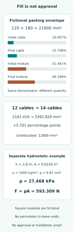
For an original geometry example, assign a usable packing rectangle 120 mm wide and 180 mm high, so its area is 21600 mm². The rectangle excludes hypothetical compression hardware. Place eight circular cables of 12 mm diameter and four of 20 mm diameter within the accounting example. Their summed cross-sectional area is 2161.416 mm², or 10.007% of that rectangle.
This ratio is a cable-area fraction, not a sealing-system approval. It leaves out the module bodies and fillers that occupy the remaining area. It also says nothing about cable spacing, allowed jacket materials, frame depth or the compression arrangement. A low ratio may appear to offer spare capacity even when the approved module layout cannot accommodate the proposed cable.
Track the changed ratio and the unchanged requirement
Add two fictional 28 mm diameter cables. Their area is 1231.504 mm²; total cable area becomes 3392.920 mm² and cable count rises from 12 to 14. Against the same 21600 mm² packing rectangle, cable-area fraction becomes 15.708%, an increase of 5.701 percentage points. It is not an increase of 5.701% relative to the original value.
The arithmetic is deliberately independent of a real product's packing rules. If someone instead divides by the external frame dimensions, the reported percentage changes without changing a single cable. A review should therefore ask what area the denominator represents and which approval condition, if any, actually uses that quantity. A persuasive percentage cannot replace a defined configuration.
Count module footprints without mistaking them for approval
Assign square counting modules of side 20 mm to the eight small cables and side 30 mm to the four larger ones. Their summed footprints are 6800 mm², or 31.481% of the fictional grid. Two added 40 mm squares bring the sum to 10000 mm², or 46.296%. These arbitrary square sizes are not manufacturer cable ranges or a proposed installation drawing.
The remaining 11600 mm² is unallocated in this bookkeeping, not authorized empty space in a sealed transit. Suitable blank modules, stays and compression provisions belong to the actual approved system. Even an area sum below the grid area does not prove that the shapes tile it with the required row arrangement. Geometric capacity and qualified sealing performance remain separate questions.
Interpret water pressure as a load, not a rating
In a separate statics example, assume differential freshwater pressure over an effective projected area of 0.12 × 0.18 = 0.0216 m². Its centroid is 2.8 m below the free surface. With density 1000 kg/m³ and g = 9.81 m/s², centroid pressure is 27.468 kPa and resultant force is 593.309 N. For a flat vertical rectangle under linear hydrostatic pressure, centroid pressure gives the total force.
No test has been performed and no seal capacity follows from that force. It does not check local leakage paths, frame attachment, cable restraint, pressure direction or duration. The effective pressure-bearing geometry in a real installation may differ from the counting rectangle. The calculation merely illustrates why an assembly carries mechanical demand even when the cable-area fraction is small.
Treat opening and reinstatement as a configuration change
A new cable can require moving existing modules, disturbing compression and changing access to previously inspected surfaces. The final evidence must follow what was actually disturbed, rather than documenting only the added cable. Comparing dated before-and-after layouts can reveal a displaced blank, a substituted module or an unrecorded cable that a total count would miss.
Z28 links installed and reinstated transits to manufacturer requirements and type approval, and requires disruption to be recorded in the register. That is a useful change boundary. A photograph taken before reopening cannot certify the resealed condition; the earlier evidence remains historical, while the altered assembly needs its own applicable completion record.
Inspect interfaces that the area calculation cannot see
A front view may show a neatly packed opening while hiding misfit around a jacket or a defect at the structure interface. Inspection therefore needs the approved arrangement and access appropriate to the relevant interfaces. Module identity, cable outside geometry and the prescribed compression evidence should be reconciled, rather than inferred from a visually dense packing pattern.
This discussion does not provide a tightening sequence or interchangeability rule. Different products use different features, tools and acceptance indicators. The current manufacturer instructions and certificate restrictions belong to the selected assembly. An unrelated module of the same colour or nominal size cannot be accepted solely because it fills the visible hole; its performance and compatibility are separate claims.
Maintain a register that points to the installed transit
A useful record begins with an unambiguous transit identifier and location. It connects the applicable drawing and approval references with the installed cable and component arrangement, then preserves later openings and reinstatements. This allows a surveyor or maintenance team to identify which physical assembly a change entry describes, especially when several similar frames sit beside each other.
The practical difficulty is often the join between documents: a work order may name a compartment, a cable list a circuit, and a drawing a frame coordinate. Those labels need a verified connection. A complete-looking register with the wrong transit identity is weaker evidence than a clearly marked unresolved item. Administrative completeness alone cannot establish the condition of the boundary.
Report capacity, conformity and condition as different outcomes
A geometry check can quantify assigned areas; a conformity check compares the real arrangement with the applicable approval; an inspection records observed installation condition. Each answers a different question. Their outputs should not be compressed into a single fill percentage, particularly after modifications that disturb parts of the assembly beyond the new cable itself.
The original example changes cable-area fraction from 10.007% to 15.708% while assigned module allocation changes from 31.481% to 46.296%. Neither number proves fire or water integrity. The separate 593.309 N resultant is an assigned demand, not a seal rating. A defensible change record shows the final configuration and the evidence for its actual boundary duties.
Sources
- IACS UR Z28 — Surveys of Watertight Cable Transits. October 2020, Corr.1 June 2021; current official landing entry checked 8 October 2026 — §§1–4, application, register, installation and surveys
- Roxtec — Sealing solutions selector. Live manufacturer selector; checked 8 October 2026 — Separate fire, water, gas, electrical and installation selections