Knowledge / Shipyards and ship structures
Piping flexibility and nozzle loads: where does thermal expansion go?
Follow metal thermal expansion through supports and equipment using an original compatibility model; separate nozzle reaction, bellows pressure thrust and code acceptance.
On this page
Heating a pipe changes its preferred length. The connected system decides how that change becomes movement, elastic deformation and reactions at supports or equipment. A nozzle load therefore cannot be inferred from temperature rise alone: the layout, restraints and equipment movement determine where expansion is accommodated and where force is transferred.
Define the metal-growth problem before calculating
The question here concerns expansion of the pipe metal and the mechanical path into equipment. It differs from pressure rise caused by heating a blocked-in liquid. Both effects can exist in one system, but a pressure calculation does not identify the pipe's thermal reaction at a nozzle, and a flexibility model does not establish relief protection for trapped fluid.
IACS's Rec.177 announcement places machinery-piping quality in fabrication, installation, commissioning and functional testing. Those activities preserve the geometry and supports assumed by engineering. An installed pipe that differs from its approved routing can change the load path even when its bore, pressure rating and endpoint names remain unchanged.
Describe what each restraint actually prevents
An anchor, guide, sliding support and equipment nozzle do not impose identical constraints. A component may restrain one translation while permitting another, or resist rotation with finite stiffness. Friction, clearances and lift-off can make the active constraint set change as the system heats. The equipment itself may move with temperature, so its connection is not always a fixed point.
Spirax Sarco's explanation links expansion accommodation to anchors, supports and pipework flexibility. A mechanical model should therefore state directions, allowed movements and attachment locations. Labels alone are insufficient: a support called “sliding” on the drawing but clamped immovably in the installation no longer supplies the assumed boundary condition.
Calculate the unconstrained growth as a separate quantity
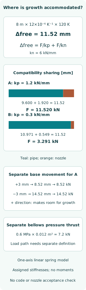
Assign an 8 m pipe an effective constant expansion coefficient α = 12 × 10⁻⁶ K⁻¹ and a uniform temperature increase of 120 K. Free growth is Δfree = αLΔT = 0.01152 m = 11.52 mm. These are teaching inputs, not certified properties for a named alloy over a specified temperature range. The calculation assumes uniform temperature and uses the selected effective coefficient over the interval.
The 11.52 mm is the growth the model would prefer without opposing axial force. It is not automatically the displacement of the equipment nozzle, the stroke of an expansion joint or a gap required at every support. Relative endpoint motion and mechanical compliance determine how much of that mismatch becomes actual movement or elastic deformation.
Solve an original one-axis compatibility model
Represent the piping layout by an assigned equivalent axial stiffness kp = 1.2 kN/mm and the equipment connection by kn = 6 kN/mm. A rigid remote anchor fixes the other end. With linear elastic behaviour and no other loads, the same reaction magnitude F passes through the two series compliances. Compatibility gives Δfree = F/kp + F/kn, so keq = 1/(1/kp + 1/kn).
Case A has keq = 1.0 kN/mm and F = 11.52 kN. Elastic accommodation within the piping is 9.60 mm and nozzle movement is 1.92 mm; their sum is 11.52 mm. The piping term opposes its free growth, while the nozzle moves with the resulting expansion. These are displacement magnitudes in a defined one-axis model, not a full three-dimensional nozzle-load vector.
Change flexibility without changing the thermal input
For case B, reduce the assigned piping stiffness to 0.3 kN/mm while retaining the same nozzle stiffness and free growth. The equivalent stiffness becomes 0.285714 kN/mm and the force 3.291429 kN. Piping accommodation is 10.971429 mm and nozzle movement 0.548571 mm. The reaction is 0.285714 times the case A value because this series system is more compliant.
This does not identify a real loop size or prove that adding a bend will achieve the assigned stiffness. A rigid nozzle in the original case would instead give F = kpΔfree = 13.824 kN. Finite equipment compliance therefore matters even in the simple model. None of these reaction magnitudes is compared with an allowable nozzle load, so the cases are neither accepted nor rejected.
Include relative endpoint movement with its sign
Suppose the equipment's base moves 3 mm in the direction that makes room for the pipe's free expansion. The mismatch becomes 11.52 − 3 = 8.52 mm. Keeping the case A series stiffness gives an 8.52 kN reaction. If the base instead moves 3 mm in the opposite direction, mismatch is 14.52 mm and reaction 14.52 kN.
These are separate imposed-base-motion cases, not extra nozzle deflections to add after solving the original compatibility equation. The sign convention must be shown on the model. Subtracting two unsigned growth magnitudes from different axes can conceal an increased load. Real vessels may also introduce hull movement, equipment rotation and changing support locations that a single scalar cannot represent.
Recognize when the linear model loses its boundary conditions
A sliding support that sticks, a gap that closes, or a restraint that lifts off changes the system stiffness and sometimes the force direction. Weight, fluid contents, insulation and pressure add other load components. A hot condition is therefore not always found by multiplying one cold stiffness by one thermal displacement, especially where contact or friction depends on the path taken.
Rec.177 section 7 addresses installation strain, support and alignment, including equipment-interface checks. Its December 2023 text is installation-quality guidance with a defined scope; it does not supply the equivalent stiffnesses used here. Preserving the approved support arrangement is part of making an analysis relevant to the installed system, rather than merely having a correct mathematical solution.
Keep expansion-joint pressure thrust on its own load path
An expansion device can reduce thermal stiffness while introducing or redirecting pressure thrust. For a separate invented bellows example, assign gauge differential pressure p = 0.6 MPa and effective thrust area Aeff = 0.012 m². Then pAeff = 7200 N = 7.2 kN. Effective area is supplied by the component design; it is not assumed equal to pipe-bore area.
The 7.2 kN is not automatically added to the preceding thermal nozzle force. Anchors, tie rods and the particular joint arrangement determine where the pressure thrust is carried and how directions combine. The manufacturer tutorial highlights this anchoring and guiding issue. Bellows movement capability, fatigue, pressure and installation limits need their own applicable design evidence.
Separate the teaching equations from a code assessment
A piping assessment needs the governing rules, material and component properties, geometry, relevant load cases, stress definitions and acceptance criteria. Equipment checks also need the manufacturer's allowable forces and moments, coordinate system and permitted combinations. A low pipe stress does not necessarily establish acceptable nozzle loading, and a low nozzle reaction does not establish every piping stress or fatigue requirement.
ASME's current public page identifies B31.3-2024 and includes flexibility among its topics. Only that overview was accessed; the full paid code was not. Neither its publication nor IACS Rec.177 automatically selects the controlling edition for a ship's contract. The scalar spring calculation is not a B31.3 compliance check or a classification submission.
Report where movement goes and what was verified
A useful result connects each temperature and equipment movement to the calculated displacements, support reactions and nozzle forces and moments in stated axes. It identifies active restraints, gaps and friction assumptions, then checks the installed arrangement against them. Cold alignment, hot movement and any changes after commissioning should remain traceable to the configuration actually assessed.
The original examples show free metal growth, compatibility sharing and the effect of relative base motion; the separate bellows calculation shows a pressure-thrust magnitude. They provide no support-spacing prescription or allowable load. Their practical lesson is that accommodating expansion is a system task: a small local movement can coexist with a substantial transferred force, and reducing one stiffness does not settle every load path.
Sources
- IACS — Recommendation to promote shipbuilding quality of machinery piping systems. Official announcement of Rec.177, checked 8 October 2026 — Fabrication, installation, commissioning and functional-test scope; companion to hull-quality Rec.47
- IACS Recommendation 177 — Shipbuilding and remedial quality standard for machinery piping systems. December 2023, official 37-page document — Section 1 scope and precedence; section 7 piping support, spacing and installation
- Spirax Sarco — Pipe Expansion and Support. Official manufacturer engineering tutorial accessed 8 October 2026 — Thermal expansion, pipework flexibility, anchor/guide functions and bellows pressure thrust
- ASME — B31.3 Process Piping. Official current product page identifies B31.3-2024 on 8 October 2026; older URL presented a stale 2022 page and was not used for edition selection — Design and fabrication scope, flexibility and stress-intensification topics; no detailed compliance clauses reproduced