Knowledge / Shipyards and ship structures
Brittle fracture in ship structures: Charpy energy, temperature and fracture toughness
Distinguish Charpy absorbed energy from fracture resistance and crack driving force, with independent temperature-test and central-crack examples that produce no acceptance limit.
On this page
A steel structure can carry a substantial load yet remain vulnerable to unstable crack extension under an unfavorable combination of temperature, flaw geometry and stress. Charpy impact results help characterize material behavior, but they do not directly answer whether a particular crack in a ship will remain stable. The distinction is between what a specimen test measures and what a structural assessment needs.
Separate crack formation from unstable extension
Fatigue concerns damage and crack growth under repeated loading. Brittle fracture concerns rapid unstable extension with limited large-scale plastic deformation in the relevant event. A fatigue crack can become the starting flaw for brittle fracture, but a cycle-count calculation and an instability assessment answer different questions. Neither nominal strength nor the absence of visible general yielding alone establishes adequate fracture resistance.
For ferritic steels, temperature, microstructure, loading rate and crack-tip constraint can influence the competition between plastic deformation and cleavage. The relevant temperature is the material temperature at the critical location and time, not automatically the weather report or a warm engine-room reading. A hull detail also carries geometric and welding history; its behavior cannot be reduced to the grade name printed on one certificate.
Read Charpy energy as a test result
A conventional Charpy V-notch test breaks a specified notched specimen by impact and reports absorbed energy in joules. The notch geometry, specimen size, orientation, test temperature and material region matter to the result. The energy includes deformation and fracture during that test; it is not simply a local material constant independent of how the specimen was made and loaded.
TWI's Charpy explanation distinguishes this absorbed-energy indication from a direct fracture-toughness value. A machined notch does not reproduce every feature of a sharp service crack, and a small specimen's constraint differs from some thick structural details. Passing an applicable Charpy requirement remains meaningful within its specification. The error is extending that bounded acceptance into an unsupported prediction for every flaw, thickness, weld and operating temperature.
Compare like specimens and retain the temperature
A report should identify where the specimen came from and which direction the crack traversed relative to rolling or welding. Parent metal, weld metal and heat-affected zone can have different structures and properties. A test centered on one region cannot automatically represent the weakest part of another. Sub-size results also need their appropriate interpretation; scaling energy solely by area can conceal a different constraint and transition response.
A temperature series may show a transition from lower to higher absorbed energy, with scatter at any given temperature. Three temperatures do not define a unique transition curve or guarantee the behavior between and beyond them. Record individual results as well as their average. An average can conceal one low specimen, and any applicable individual-value criteria must be checked under the actual specification rather than invented after seeing the data.
Summarize an original fictional Charpy series
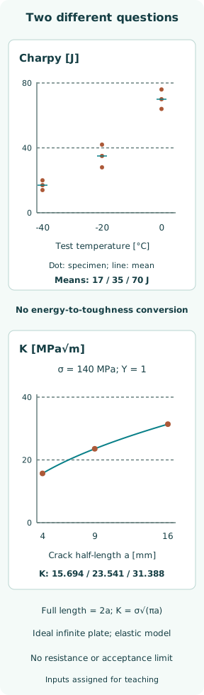
Assign comparable fictional full-size specimens results of 14,17 and 20 J at−40°C;28,35 and 42 J at−20°C; and 64,70 and 76 J at 0°C. The means are 17,35 and 70 J. The within-triplet ranges are 14–20,28–42 and 64–76 J, with widths 6,14 and 12 J. All nine values are invented teaching inputs; no steel heat, class requirement or laboratory certificate is represented by them.
The original figure shows the individual values and mean at each assigned temperature without fitting a curve. The middle set has the widest spread even though its mean lies between the others. These data alone do not yield a fracture-toughness distribution, a lower-bound design value or a qualified transition temperature. There is no acceptance line: selecting one would require the appropriate material, test and project criteria.
Introduce a separate crack-demand calculation
Now leave the Charpy series entirely aside. Consider an ideal infinite flat plate with a central through-thickness crack of full length 2 a under uniform remote tensile stress σ. Assume mode I opening, linear elasticity and small-scale yielding. For this ideal geometry, the crack-tip stress-intensity demand is K = σ√(πa), equivalent to geometry factor Y = 1. Length a is the half-length, and it must be in metres when K is expressed in MPa√m.
TWI's stress-intensity compilation emphasizes that the geometry factor and solution validity are part of the calculation. The ideal infinite plate is therefore a teaching boundary, not a default representation of a ship's bracket or weld. Finite width, surface-crack shape, local stress concentration and bending would require their appropriate solutions. No Charpy energy appears in this equation or supplies its inputs.
Calculate sensitivity without claiming crack acceptance
Set σ = 140 MPa and choose half-lengths 4,9 and 16 mm, corresponding to full crack lengths 8,18 and 32 mm. The calculated K demands are 15.694,23.541 and 31.388 MPa√m. Increasing half-length from 4 to 9 mm multiplies demand by 1.5; increasing it from 4 to 16 mm doubles demand. The square-root relation explains the ratios. These are applied demands for separate hypothetical configurations, not a crack-growth history or a time forecast.
At the fixed 9 mm half-length, raising remote stress to 175 MPa gives K = 29.426 MPa√m, a 25% increase in both stress and demand. Nothing here says whether any case fractures, because no applicable material-resistance value has been supplied. A numerical K demand is not itself fracture toughness. A seemingly low remote stress can still require investigation when a relevant flaw exists; the comparison needs valid resistance and structural inputs.
Keep toughness measures and validity conditions explicit
Fracture resistance can be characterized through measures such as K, crack-tip opening displacement or the J-integral under defined test and assessment conditions. They have different units and validity requirements. Charpy absorbed energy in joules is not the J-integral merely because both use the letter J; the latter is an energy-per-area quantity. Nor is every reported K result automatically a valid plane-strain KIC value.
TWI's fracture-testing description identifies K, CTOD and J as fracture-mechanics outputs under relevant test methods. Specimen thickness, crack preparation, loading and material behavior affect the interpretation. Where plasticity is not small, the simple elastic demand model may not be sufficient. A complete assessment may also need plastic-collapse checks; avoiding one failure mechanism does not establish immunity to another.
Account for welds, residual stress and local material
A welded region combines changing microstructure, geometry and locked-in stress. The most relevant crack path may cross several zones. Testing one convenient coupon location or using a parent-plate average can miss the region controlling fracture. Residual stress can contribute to crack driving force even when the externally calculated nominal stress appears modest; its appropriate representation belongs to the selected assessment procedure.
The ideal plate case has no weld, finite boundary or residual-stress field. Adding a guessed multiplier to its K result would not make it a qualified welded-detail assessment. The useful next evidence is the actual flaw geometry, relevant stresses and temperature, material region and applicable resistance characterization. Detection uncertainty also matters: the measured indication is not an exact crack front, and the method must address the limits of inspection coverage and sizing.
Use test quality and applicable criteria together
A measured Charpy value depends on competent specimen preparation, conditioning, machine performance and reporting. NIST's verification programme treats machine verification, variability and uncertainty as explicit parts of impact testing. That does not mean a poor result can be discarded by appealing vaguely to scatter. An identified testing problem needs a documented disposition under the applicable method, with the original results retained.
For material selection or a detected flaw, establish the governing class and project criteria, minimum relevant service temperature, thickness, fabrication condition and assessment method. Public technical explanations support understanding; they do not provide the full current acceptance clauses of paid ISO, ASTM or BS standards. Any empirical correlation between Charpy and fracture properties has a defined material and validity scope, uncertainty and approved use; it is not a universal unit conversion.
Report the two examples as independent findings
The invented impact series establishes three means and their observed spreads at three assigned temperatures. The ideal crack model establishes how elastic demand changes with crack half-length and remote stress. There is deliberately no arrow from 17,35 or 70 J to any of the calculated K values. The two sets address different quantities and have different assumptions; their placement in one figure is a comparison of questions, not a calibration.
A real brittle-fracture conclusion requires suitable resistance evidence, representative loading and flaw characterization, the relevant temperature and a valid assessment framework. The examples produce no critical flaw size, allowable stress, material approval or fatigue life. Their practical lesson is to preserve the boundary between screening material behavior and deciding structural integrity, so that a useful certificate result does not become a claim it was never designed to support.
Sources
- TWI: What is a Charpy Impact Test?. Current public technical explanation checked 8 October 2026 — Notched high-rate absorbed-energy test, temperature dependence and prohibition on direct fracture-toughness inference
- TWI: Compilation of stress intensity factor and load limit solutions for the FITNET procedure. Article identifies presentation at FITNET 2006, 17–19 May 2006, paper FITNET 06-022; URL contains may-2008; public text checked 8 October 2026 — Stress intensity factor section: general K formulation and geometry/validity dependence
- TWI: Fracture Toughness Testing. Current public technical page checked 8 October 2026 — Fracture-mechanics testing and K, CTOD and J measures; applicable test standards and material zones
- NIST: Charpy Machine Verification Program. Current public programme description checked 8 October 2026 — High-rate absorbed energy, machine verification, variation, uncertainty and transition-curve analysis