Knowledge / Shipyards and ship structures
Slipway launching: developing buoyancy and temporary hull loads
Explore buoyancy growth, compression-only supports and temporary hull loading with an original contact-state example that cannot establish a safe launch.
On this page
During a slipway launch, buoyancy develops while the support arrangement is changing. Weight minus buoyancy gives a total vertical support demand only within a defined model; it does not say where contact remains or how the hull bends. The transition must be understood as a sequence of changing physical states.
Distinguish sliding launch from dock float-out
Wärtsilä defines traditional launching as a ship sliding under its own weight down inclined ways into water, distinguishing the equivalent float-out from a dry dock. The difference matters mechanically. In a dock, rising water and controlled support release form one transition; on ways, translation and changing immersed geometry accompany the loss of support.
A vessel that is satisfactory when fully afloat can still encounter a critical intermediate condition. This article considers a longitudinal launch conceptually. It does not cover side launching by treating the drawing as a rotated version of the same problem. The relevant support geometry, motion and stability questions must be established for the actual launch arrangement.
Establish weight and water data for each state
The launch weight includes the ship and whatever temporary equipment, liquids and cradle contributions belong to the chosen model. Its centre of gravity is as important as its magnitude. Late material additions or removals can change both. Water density and level influence buoyancy for a given immersed geometry, so a nominal displacement label does not define the launch condition.
SARC's PIAS Manual 2026 identifies ship weight and centre of gravity, cradle and slipway geometry, water level and density among longitudinal-launch inputs. It is software documentation, not a launch approval standard. No program is run here. The original example assigns forces and locations directly so that its equilibrium assumptions can be inspected without suggesting validated vessel geometry.
Declare a vertical-force surrogate and its coordinates
Let a fictional weight W = 18000 kN act at xG = 26 m. An aft support A lies at xA = 8 m and a forward support F at xF = 44 m. Coordinate x increases forward from an arbitrary aft origin; these are horizontal lever arms. For comparison only, W/g corresponds to 1834.862 tonnes with g = 9.81 m/s².
The two support resultants are idealized as vertical. A real inclined slipway requires the actual directions of normal and friction forces, plus motion and changing contact. Those features are excluded here. Assign upward buoyancy B at xB and ask only whether this instantaneous vertical-force arrangement can satisfy force and moment balance with two compression-only supports.
Solve two states while both reactions remain non-negative
Vertical balance gives RA + RF = W − B. Taking moments about A gives RF = [W(xG − xA) − B(xB − xA)]/(xF − xA). In state A, B = 0, so both reactions are 9000 kN. In state B, assign B = 6000 kN at xB = 10 m. Then RF = 8666.667 kN and RA = 3333.333 kN.
The total support falls to 12000 kN, but the forward reaction falls much less than the aft reaction because of the assigned buoyancy lever arm. With density 1025 kg/m³, the assigned 6000 kN corresponds to 596.703 m³ through B = ρg∇. That conversion checks units; it does not demonstrate that any real hull immersion produces the assumed buoyancy or its location.
Read a negative reaction as loss of the assumed contact state
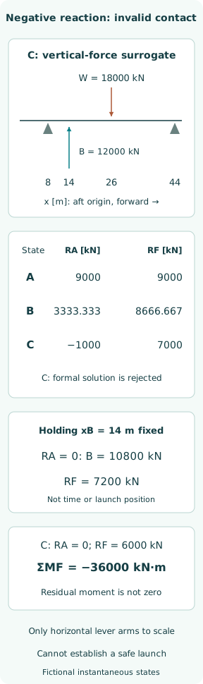
In state C, assign B = 12000 kN at xB = 14 m, retaining the same weight and support coordinates. The two-support algebra returns RF = 7000 kN and RA = −1000 kN. Their sum is 6000 kN, but the negative aft reaction would require that support to pull down on the hull. An unrestrained bearing contact cannot supply that tension.
Thus the formal solution rejects the assumed two-contact state; it is not a prediction that the aft support physically carries −1000 kN. The hull may lift there and rotate, changing immersion and buoyancy. A restraint, if actually fitted, would introduce a different physical model and its own loads. Simply retaining the negative number as an ordinary support result conceals the transition that needs analysis.
Find a threshold without claiming a launch position
For a separate local sensitivity, hold xB fixed at 14 m. Setting RA = 0 in the same equations gives B = W(xF − xG)/(xF − xB) = 10800 kN and RF = 7200 kN. This is the boundary of the assumed two-compression-contact solution. It is not a calculated travelled distance, water level, time or release instruction.
In an actual launch, xB generally changes with translation and rotation, while the support region itself may shorten or move. Freezing those variables creates an algebraic teaching threshold, not a physical trajectory. Comparing states B and C therefore does not imply that the vessel passed through the fixed-centroid threshold along a known path. Each point has explicitly assigned data.
Do not repair the model by deleting one negative number
At state C, if aft contact is removed, vertical force balance alone would set RF = W − B = 6000 kN. Yet the remaining moment about F is W(44 − 26) − B(44 − 14) = −36000 kN·m. With positive moment defined counterclockwise on a forward-right, upward-positive sketch, this is clockwise. The force-only repair leaves an unbalanced rotational demand.
That residual does not give rotation angle or acceleration because the model contains neither a new immersion solution nor rotational inertia. The SARC manual explicitly restricts its assumed cradle-pressure distribution to positive pressure because the cradle cannot exert tension. This reinforces the contact constraint; it does not validate this simpler surrogate or supply the missing dynamic and geometric calculations.
Separate global equilibrium from temporary hull bending
As another reading of valid state B, cut the point-force surrogate at x = 20 m. To the left lie RA = 3333.333 kN at x = 8 m and buoyancy 6000 kN at x = 10 m. Their total upward load is 9333.333 kN, and their moment magnitude about the cut is 3333.333 × 12 + 6000 × 10 = 100000 kN·m.
These are internal-action demands for an invented point-load beam representation, not a hull-girder stress assessment. A real ship has distributed weight and buoyancy, local cradle pressures, structural stiffness and three-dimensional load paths. Even a satisfactory global force balance can coexist with unacceptable local loading. Section strength, shell contact and supporting structure require their own geometry and approved assessment.
Connect operational evidence to the stage being assessed
A launch plan needs controlled weight information, water conditions, ways and cradle condition, movement restraints and the relevant structural and stability assessments. Measurements before release should correspond to the version of that plan, and later changes should be evaluated against the stages they affect. A correct arithmetic sheet cannot compensate for an obsolete weight or an unrecorded temporary load.
This is not an operating sequence, friction prescription or weather limit. The competent launch organization must establish the applicable site, vessel, class and local requirements. The example supplies no launch speed, stopping distance, under-keel clearance or lateral stability result. Its practical contribution is to make the assumed contact state visible before a model output is interpreted as physical support.
Conclude with the state that remains unresolved
Positive reactions in states A and B establish only that the assigned vertical balances are compatible with two compression contacts. State C shows that the same contact assumption fails. The threshold example locates an algebraic boundary under a fixed centroid, and the force-only correction exposes a remaining moment. None establishes the next actual state of a moving vessel.
The final launch judgment must cover the complete transition, including changing immersion, support contact, hull strength, motion and the receiving water area. A launching model can organize this evidence and reveal inconsistencies, but cannot by itself establish a safe launch. The useful lesson is to ask which physical state each result represents and to stop interpreting a rejected contact state as a valid load distribution.
Sources
- Wärtsilä Encyclopedia — Launching. Undated live encyclopedia entry; checked 8 October 2026 — Definition of sliding launching and distinction from dock float-out
- SARC PIAS Manual — Launch: launching calculation. PIAS Manual 2026, live developer documentation checked 8 October 2026 — Longitudinal launch inputs, pressures, forces, speeds and anti-tipping moments