Knowledge / Navigation and marine safety
Radar vectors: relative motion, true motion and reference errors
Understand radar motion through component vectors, water and ground references, sensor dependencies and worked error examples.
On this page
A radar arrow is a calculation in a reference frame. Its usefulness depends on knowing that frame, the velocity added to the measured relative motion and the age of the underlying observations. This article follows the transformations explicitly; it does not prescribe an avoiding manoeuvre.
Separate four independent display choices
A radar picture has several references at once. Display motion determines whether own ship moves across the screen; orientation determines which direction is at the top; stabilization determines the velocity reference used for calculated true motion; and vector selection determines whether a target arrow represents relative or true velocity. A north-up picture can show relative vectors, and a relative-motion picture can show true vectors. Reading one label cannot settle all four questions. Record the selected combination before interpreting a surprising arrow.
IMO resolution MSC.192(79), sections 5.20–5.23 and 5.27.2–5.27.3, adopted 6 December 2004, distinguishes these functions and requires identification of stabilization and its source. This is an equipment performance standard, not a requirement to use one screen arrangement in every encounter. Its application depends on installation and approval history. On an actual set, the operating manual determines the available combinations and the behaviour after a source failure.
Write the transformation before reading the arrow
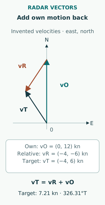
Use a local horizontal frame with east and north components, all in knots. Let vTg be target velocity over ground and vOg own-ship velocity over ground. The measured relative velocity is vR = vTg − vOg. Recovering target ground velocity requires adding vOg back: vTg = vR + vOg. Relative radar measurements do not, by themselves, reveal which part of that motion came from the target and which came from own ship.
Angles in the examples are clockwise from true north, so east speed is V sin C and north speed is V cos C. Using the mathematical convention of angle from the east axis without changing these equations rotates the interpretation. A velocity vector is also different from a displacement: the latter requires a stated time interval. Arrow length without its vector-time setting cannot be converted to knots.
An original two-component example
Assume own ship makes 12.00 kn due north over ground, so vOg = (0.00, 12.00). A steadily tracked target has vR = (−4.00, −6.00) kn. Adding the vectors gives vTg = (−4.00, 6.00) kn: 7.21 kn on 326.31°T. Its relative vector is 7.21 kn on 213.69°T. The equal magnitudes are a coincidence of these chosen numbers; the directions and physical meanings are different.
At a six-minute vector time, one tenth of an hour, the relative displacement is (−0.40, −0.60) NM and the ground displacement is (−0.40, 0.60) NM. Both arrows are 0.721 NM long. Shortening vector time to three minutes halves their lengths without changing either estimated velocity. These calculations assume constant velocities, synchronized data and a stable track; they do not predict a turn or establish a passing distance.
Sea stabilization introduces a water reference
Let own-ship water velocity be vOw and local current be cO, so vOg = vOw + cO. Adding vOw to the measured relative vector produces vTg − cO. This equals the target’s own water-relative velocity only when the target experiences the same current vector and the own-ship water velocity is represented correctly. Current shear, leeway and a single-axis log can defeat that assumption.
For a second original example, own ship has vOw = (0, 10) kn and current cO = (2, 0) kn. A fixed beacon has ground velocity zero, so its relative velocity is (−2, −10) kn. Ground stabilization reconstructs zero; sea stabilization reconstructs (−2, 0) kn. The westward arrow does not mean the beacon is moving. It is the fixed object viewed in the assumed moving-water frame.
A true vector is not necessarily a heading
A ground track indicates translation of a reference point. Heading describes orientation of the hull. They can differ under current and leeway, and a target may yaw without immediately changing its translational track. Sea-stabilized motion can help interpret aspect when its assumptions hold, but the arrow is not a direct observation of the target’s fore-and-aft axis.
The UK MGN 379 Amendment 1, section 3.6, updated 9 January 2024, discusses stabilization choices for different navigation tasks. Treat that as UK operational guidance and read it with the actual sensor arrangement. In particular, an ordinary GNSS COG value must not be relabelled as heading; heading from a suitable separate or multi-antenna sensor is a different measurement.
Own-ship input error appears in every reconstructed target
In the simple additive transformation, an own-ship velocity error δv adds the same δv to every reconstructed true target velocity. Suppose a fixed object is processed with an eastward own-speed bias of 0.60 kn. Its reconstructed ground vector acquires 0.60 kn eastward. Over a twelve-minute vector time that corresponds to a 0.120 NM arrow, although the raw object remains fixed in the real world.
Heading error is more complicated because it can rotate measured bearing coordinates as well as the own-speed vector. At 15 kn, a 2° heading offset produces a transverse component of approximately 15 sin 2° = 0.523 kn in the own-speed input. This is an input-sensitivity example, not the total error of a particular radar. Correlated heading errors can affect chart overlays and another display at the same time.
Distinguish prediction from motion history
A vector projects an estimated velocity forward for a selected interval. A trail records earlier displayed positions, subject to the chosen reference and processing. After a manoeuvre, a curved trail and a straight vector are not necessarily contradictory: one represents history and the other a current estimate. Old and new velocity samples may also coexist while the tracker settles.
Changing stabilization or resetting trails can change the visible picture without any physical manoeuvre. A useful training comparison keeps raw observations, vector time, motion mode, stabilization and source health together. Annotate when any setting changed. Otherwise a screenshot collected after the event can be mistaken for the information actually available before it.
Test the reference chain instead of selecting the nicest picture
An original diagnostic exercise begins with several confidently identified fixed echoes and one moving target. Compare their relative movements, reconstructed true vectors and displayed sensor sources. A common residual on fixed echoes suggests a shared input or reference problem; one isolated residual suggests identification, tracking or local-target issues. Neither pattern proves a unique fault, but the distinction makes the investigation testable.
Avoid switching modes until the arrows look plausible and then treating plausibility as validation. Do not assume two screens are independent when both consume the same heading and speed. Do not read sea-stabilized speed as SOG, treat vector length as clearance, or infer another vessel’s intention from a smooth arrow. The practical outcome is a defensible statement of which motion is being shown, which assumptions support it and which observations could contradict it.
Sources
- MSC.192(79): Revised performance standards for radar equipment · IMO · Source check date: 2026-10-06
- MGN 379 (M+F) Amendment 1 · UK MCA · Source check date: 2026-10-06