Knowledge / Risk analysis methods
Dynamic-positioning FMEA and proving trials: linking failure analysis to evidence
Connect DP failure assumptions, remaining force and moment capability, system configuration and proving-trial evidence without treating a test count as proof of fault tolerance.
On this page
A dynamic-positioning FMEA predicts how failures can affect a vessel’s ability to maintain position and heading. Proving trials test important parts of that prediction in a defined configuration. The two are complementary: an analysis without evidence can preserve false assumptions, while trials without a clear failure model can produce a large record that does not answer the essential redundancy questions. The link between each predicted failure effect and its verification is the central subject.
Identify the applicable guidance and system boundary
The preamble of MSC.1/Circ.1580 recommends its application to vessels and units constructed on or after 9 June 2017 and explains the relationship with the earlier MSC/Circ. 645. The actual vessel’s Administration, class and approval basis remain necessary. Do not infer the governing requirements from a DP class label without the relevant documentation and construction history.
The DP system includes more than its control computers. Power generation and distribution, propulsion and thrusters, position references, sensors, communications and supporting machinery can affect the required result. DNV’s public DP overview describes this integrated mechanical, electrical and electronic scope. A cooling or control-power dependency can matter even when it is physically distant from the DP console.
Separate worst-case failure from design intent
The definitions in MSC.1/Circ.1580 distinguish the identified worst-case failure from the minimum DP capability intended to remain afterward. The first is an analysis result about a relevant fault’s detrimental effect; the second is the design requirement against which that result is judged. A document that uses the two expressions interchangeably can obscure whether the required residual capability has actually been demonstrated.
State the analyzed configuration and the single-failure criteria applicable to the equipment class. The relevant fault is not necessarily the loss of the largest individual thruster. One shared cause can remove a group, or an interface can propagate an effect beyond the assumed group boundary. The consequence must be traced through the supporting systems rather than inferred from installed equipment count.
Link the analysis to proving trials
For equipment classes 2 and 3, MSC.1/Circ.1580§5.1.2 calls for an FMEA and confirmation by proving trials, with the analysis kept current. IMCA’s M166 public summary likewise identifies redundancy, configuration and practical validation as central subjects. Neither statement makes an unstructured demonstration equivalent to a complete verification programme.
For each relevant test, retain the failure hypothesis, predicted effect, configuration, acceptance criterion and observations required to distinguish success from an unexpected result. The approved test method must represent the intended failure adequately and control the hazards of testing. A simulated input can be appropriate for one question while leaving another physical failure path outside its scope. The analysis should explain that boundary.
Use force and moment together in a simple example
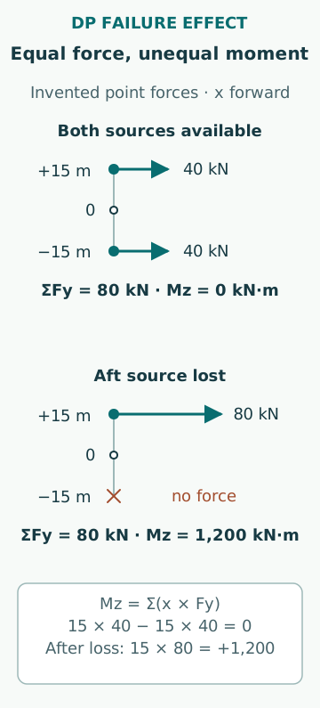
Imagine two ideal lateral force sources at longitudinal coordinates x = +15 m and x = −15 m relative to a chosen reference, each applying 40 kN in the same transverse direction. Their combined lateral force is 80 kN, while yaw moments cancel: +15 × 40 −15 × 40 = 0 kN·m. Suppose the aft source is lost and the forward source can increase to 80 kN. The lateral force can again reach 80 kN, but its yaw moment becomes+1,200 kN·m.
Thus matching the required force magnitude alone does not establish the same force-and-moment capability. This is an invented planar statics example with point forces, fixed directions and no other actuators. Real DP capability also depends on thrust direction limits, interactions, environmental loading, power and control response. The example is not a vessel capability plot, a thrust-allocation design or an approved operating condition.
Preserve configuration-dependent failure effects
A failure analysis applies to the connections and operating states it represents. Bus configuration, available generators, thruster selection, cooling paths and control-power arrangements can change propagation and remaining capability. A test performed with one supporting service supplied independently may not validate a configuration in which that service is shared. The configuration record therefore belongs with the result.
Also retain the state of protective and compensating functions. A fault may be correctly detected but isolated too broadly, or a transfer may preserve power while interrupting a control path. An apparently successful steady endpoint can conceal an unacceptable transient. Use the accepted excursion and functional criteria from the actual assessment rather than inventing a universal position or heading tolerance.
Check observations against the predicted sequence
A useful trial record should allow the observed sequence to be reconstructed: the represented initiating condition, detection, isolation, load redistribution, remaining machinery and relevant position/heading response. Clock alignment, signal quality and the distinction between commands and physical responses affect that reconstruction. A list of final alarm messages is not the same as a causal time record.
If observed effects differ from the FMEA prediction, the discrepancy is evidence to investigate. It may reflect an incomplete model, a different configuration, a degraded item or a test that did not represent the intended failure. Do not simply revise the predicted result to match the test without explaining the mechanism. The corrected analysis and any further verification should address the actual source of the difference.
Distinguish initial validation from continuing assurance
IMCA’s2020 clarification of annual trials distinguishes proving-trial validation from subsequent testing arrangements and explains why rolling tests are not simply a fixed percentage of an overall annual programme. The current applicable rules, accepted programme and relevant document revisions must govern the actual vessel. Historical emergency allowances or another vessel’s schedule are not general permission to reduce testing.
The analytical distinction is stable: proving trials support the failure model and redundancy concept, while continuing assurance asks whether the relevant functions remain in the intended condition. Maintenance evidence can support a defined question if its scope and acceptance are suitable, but cannot be assumed to replace every required test. Keep each evidence source tied to the function and mode it actually addresses.
Treat a modification as a potential change to the proof
Changing a switchboard setting, control version, cooling arrangement or connected consumer can alter the boundary on which a previous conclusion depended. The effect may be important even when the new component performs its own local function correctly. A current FMEA should trace such changes to the affected failure paths, assumptions and verification evidence.
The review should identify which existing results remain applicable, which need targeted re-verification and whether a broader proving programme is required by the governing basis. Preserve old results as records of the earlier configuration rather than silently relabelling them as current. A nominal like-for-like replacement still needs the relevant compatibility and restoration evidence; matching a model label alone may not establish identical behaviour.
Make the final conclusion narrower than the evidence
A defensible report states the analyzed configuration, failure criteria, identified worst-case effect, remaining capability and the evidence supporting the conclusion. It records unresolved findings and any limits imposed by test representation or operating conditions. The existence of an FMEA report or a large number of completed trial sheets is not by itself an assurance of every future operation.
Common mistakes are equating installed redundancy with demonstrated fault tolerance, checking force without moment, transferring a result between configurations and treating a diagnostic alarm as proof of successful recovery. DP assurance is strongest when the physical failure model and the observed response agree for the intended scope. This educational discussion provides no instructions for introducing live faults or conducting trials near an operational hazard.
Sources
- MSC.1/Circ.1580,16June2017 · IMO;copyhostedbyRepublicofMarshallIslandsregistry · Source check date: 2026-10-06
- MSC.1/Circ.1580 officialUSCGcopy · IMO;USCoastGuardhost · Source check date: 2026-10-06
- Code of practice on FMEA,M166Rev3May2024 · IMCA · Source check date: 2026-10-06
- IN1496:Clarification of DP annual-trial requirements,2April2020 · IMCA · Source check date: 2026-10-06
- Dynamic positioning assurance overview · DNV · Source check date: 2026-10-06