Knowledge / Risk analysis methods
Linking event trees and support-system fault trees
Connect sequence success criteria to fault-tree top events while preserving shared basic-event identity, success complements and configuration boundaries.
On this page
An event-tree heading may represent the successful delivery of cooling, electrical power or isolation. A supporting fault tree explains how that function can fail. Linking the two is more than copying a probability into a spreadsheet. The combined model must preserve the same function, demand, time window and shared causes on every path. Otherwise two individually plausible models can produce an inconsistent accident sequence when joined.
Match the two ends of the interface
NRC’s PRA description connects event-tree functional headings with fault-tree analyses. Before connecting them, write the heading’s success criterion and the fault tree’s failure criterion side by side. Cooling available and pump starts are not logical complements. One describes a delivered service; the other describes only one equipment response that may contribute to it.
IAEA SSG-3 (Rev. 1), paragraph 5.73 expressly relates the failure criterion to the inverse of the sequence success criterion. As a modelling principle, this means that the fault tree must fail whenever the required service is not delivered under the defined conditions. It does not mean importing nuclear criteria into a ship analysis.
Preserve demand and mission definitions
Suppose a heading requires a consumer to receive at least a specified flow within a defined response time and retain it through a stated mission. A fault tree limited to failure to start omits failure to continue running and failures elsewhere in the delivery path. Conversely, a long-mission failure probability can overstate a short demand if it is used without matching the duration and failure model.
Record the demand mode, mission duration, required capacity, environmental state and initial configuration at the interface. Two branches can use the same physical equipment but different success criteria. A partial flow might suffice after one initiator and fail after another. Reusing a fault-tree name is reasonable only if its logic or boundary conditions preserve those differences.
Give one physical event one consistent identity
If two functions depend on the same distribution board, its relevant failure event must retain one identity across their supporting trees. Calling it supply-loss-A in one tree and supply-loss-B in another can accidentally turn one physical event into two independent events. Using different diagram instances is harmless only when the model still links them to the same underlying event definition.
The converse error is also possible. Two separate pumps should not be merged merely because their equipment type and numerical failure probability match. Event identity describes what happened to which item, in which mode and exposure; it is not a shortcut for similar data. Separate items can share a common-cause mechanism while still retaining their distinct local failure events.
Reduce repeated logic before numerical multiplication
The Boolean rules collected in NASA’s Fault Tree Handbook, Appendix A include idempotence and absorption. Consider an original small interface model: function X fails if shared support U fails or local item A fails; function Y fails if U fails or local item B fails. Thus FX = U ∨ A and FY = U ∨ B.
A sequence requiring both function failures has logic (U ∨ A) ∧ (U ∨ B) = U ∨ (A ∧ B). The repeated support failure is still one event. Its appearance in two trees does not justify squaring its probability. The reduced expression also shows why improving only local A or B cannot remove the contribution from U. This is a logical conclusion before any failure numbers are assigned.
Check an illustrative probability against the logic
For this calculation only, assume U, A and B are mutually independent basic events on the same defined exposure, with probabilities 0.010, 0.020 and 0.030. The probability of U or both local failures is 0.010 + 0.020 × 0.030 − 0.010 × 0.020 × 0.030 = 0.010594. The overlap subtraction is required because the event U can coexist with A and B.
Equivalently, partition by support status: 0.010 + 0.990 × 0.020 × 0.030 gives the same answer. The two complete function-failure probabilities are 0.0298 and 0.0397; multiplying them gives 0.00118306, which is not the joint failure probability. Independence of the three basic events does not make the two compound function-failure events independent, because both contain U.
Carry success branches as well as failure branches
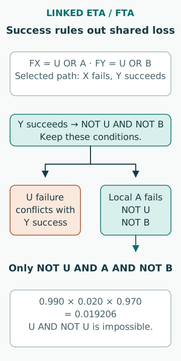
A sequence with X failure and Y success has logic (U ∨ A) ∧ not(U ∨ B). Applying the complement and distributive rules reduces it to not U ∧ A ∧ not B. Under the same illustrative independent-basic-event assumptions, its probability is 0.990 × 0.020 × 0.970 = 0.019206.
This path cannot contain U failure, because Y success rules it out in the stated model. Retaining a cut set that contains both U and not U creates an impossible sequence. A linking implementation should therefore preserve success conditions or use a justified equivalent treatment; simply concatenating lists of failure combinations can overlook those constraints. The same issue can arise when a successful earlier function establishes that a shared support was available.
Represent configuration changes explicitly
A maintenance state can remove one train, alter an alignment or change which support supplies a function. A boundary-condition switch can select the corresponding logic, but its meaning and permitted combinations must be documented. A switch is not an unexplained adjustment factor applied until the final risk number looks reasonable.
Known unavailability in the analysed configuration is a state condition rather than a fresh small random failure probability. Conversely, future unavailability over a mission requires a probabilistic or time-dependent model. Mixing a known outage with an average annual unavailability can give credit for a train that is explicitly out of service on the path. The interface should make this distinction visible to both the sequence analyst and system analyst.
Check composite data and common causes
A supplier’s complete-function failure estimate may already include support loss or diagnostic failure. Adding an explicit support tree without reconciling its boundary can count the same mechanism twice. A data field should therefore identify included components, failure modes, repair assumptions and test coverage. A numerical value detached from that scope is not a reliable interface.
Similarly, explicitly modelled functional dependence should not be hidden again inside a generic common-cause term. Separate the shared utility mechanism from residual common-cause susceptibility of the local items. If their overlap is uncertain, state and test the modelling alternatives. Naming the two mechanisms differently does not establish that they are disjoint or statistically independent.
Review the linked model as one argument
A practical interface review follows selected complete sequences down to basic events and back to the physical arrangement. Check that repeated event identifiers truly refer to the same occurrence, that distinct items remain distinguishable, that success branches exclude incompatible failures and that state switches represent the analysed mode. Small hand-solvable cases can verify the linking behaviour before relying on a large model.
Retain an interface record showing the heading, success criterion, linked top event, boundary conditions, exposure basis and evidence source. Changes to a support system can then be traced to every affected sequence. The benefit of linkage is a coherent explanation of how system failures combine, not a numerical precision that exceeds the quality of the functional definitions or data.
Sources
- Probabilistic Risk Assessment · US NRC · Source check date: 2026-10-07
- SSG-3 (Rev. 1), 2024 · IAEA · Source check date: 2026-10-07
- Fault Tree Handbook with Aerospace Applications, Version 1.1 · NASA · Source check date: 2026-10-07