Knowledge / Risk analysis methods
Functional and equipment FMEA: choosing a boundary that matches the question
Connect required functions to equipment failure modes, interfaces and operating conditions without mistaking a complete parts list for complete failure coverage.
On this page
An equipment list tells an analyst what has been installed. A functional description tells the analyst what the system must achieve. Both are needed, but they organize an FMEA differently. Starting only from components can miss an unsuitable or mistimed system output even when each component works as specified. Starting only from broad functions can hide the physical paths through which a failure propagates. The useful approach connects the two levels with explicit boundaries and success criteria.
Write a function that has a measurable outcome
IEC 60812’s public scope describes FMEA as a way to identify how items or processes fail to perform their functions and the resulting local and wider effects. A function should therefore name an outcome, its recipient and the conditions that make it successful. “Cooling system operates” is less informative than “remove the required heat while maintaining the specified consumer temperature and fluid condition in the stated mode.”
The latter description exposes different kinds of failure: no service, insufficient service, excessive cooling, wrong destination, contaminated fluid or service arriving too late. It also separates the required result from one possible implementation. Do not invent a numerical limit just to make the sentence precise; use the requirement or identify the unresolved limit as an analysis gap.
Choose an analysis level deliberately
NASA’s2019 FMECA development discussion describes an early functional view that becomes more detailed as the design develops, with some elements initially treated as black boxes. That progression is useful beyond the aircraft example when its application boundary is kept explicit. Early analysis can identify which outputs are essential before every internal component has been selected.
A later equipment FMEA asks how pumps, valves, sensors, heat exchangers, power supplies and other items can fail and how those failures affect the required outputs. More detail is useful only if it improves the question being answered. A long list of internal parts with identical unexplained end effects may create work without improving confidence in the system-level conclusion.
Map functions and components in both directions
One function can depend on several components, and one component can support several functions. A cooling pump may support more than one consumer; a control-power supply may support flow control, indication and a protective action. Mapping only each component to one headline function can miss those shared dependencies. The map should also retain material, energy and information interfaces.
Read the map both ways. Starting from a required function, ask what physical paths and services deliver it. Starting from a component failure mode, ask every function and operating mode it can affect. A row about loss of a pump should not end at pump stopped if the actual question is which consumers lose adequate heat removal and how quickly that matters.
Use a capacity calculation to define functional success
The energy balance described in the DOE heat-transfer handbook provides a simple teaching example. Assume a cooling stream with constant specific heat 4.00 kJ/(kg·K) may rise by 8.00 K across a consumer while removing 1,000 kW. Under a steady single-phase model with no other energy paths, the required mass flow is 1,000/(4.00 × 8.00) = 31.25 kg/s.
If the available flow were 25.0 kg/s under the same assumptions, it would remove 800 kW at that temperature rise. The shortfall is a functional failure even if the pump is running and every component meets its own local specification. These invented values are not ship operating limits. Actual success also depends on inlet temperature, pressure, distribution, heat-transfer capability and the approved consumer requirements.
Do not infer redundancy from component count
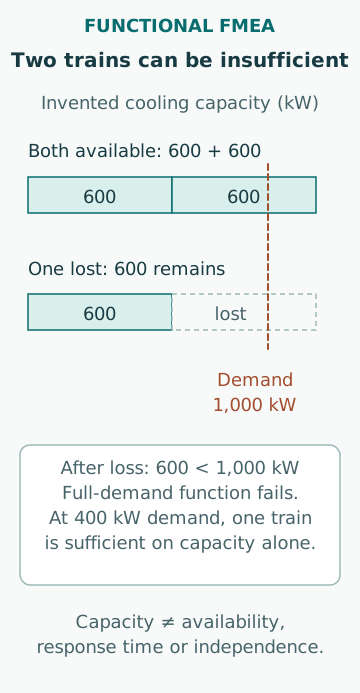
Consider a separate system with two hypothetical cooling trains, each capable of 600 kW in the stated condition. With both available their combined capacity is 1,200 kW against a 1,000 kW demand. Loss of either leaves 600 kW, so the remaining train cannot meet the full demand despite the presence of two trains. Calling the arrangement fully redundant would hide the success criterion.
In another operating mode with 400 kW demand, one 600 kW train may be sufficient on capacity alone. That does not prove its availability, response or independence. The mode distinction belongs in the FMEA because the same local failure can have a different end effect. Do not merge those cases into one row unless the retained explanation makes the different outcomes clear.
Trace local, next-level and end effects
The public NASA FMECA worksheet definitions distinguish local effects, effects at the next higher level and the end effect. This gives a useful discipline for describing propagation. A sensor bias is local; an incorrect control decision can be the next-level effect; and inadequate service at a consumer can be the system effect. Each link needs a credible mechanism, not an automatic jump to the worst imaginable outcome.
Also consider outputs that are wrong rather than absent. A stuck indication can conceal a changing process, and a valve passing when commanded closed can connect boundaries that are meant to be separate. If compensation is credited, state its capacity, response and supporting assumptions. An end effect described as no consequence because of backup is incomplete when the backup’s relevant conditions are not identified.
Keep interface failures and shared causes visible
GSFC-HDBK-8004 explicitly includes propagation and common-cause susceptibility within its FMECA framework. Used as general analytical guidance, this reminds the analyst that two successful component descriptions do not guarantee a successful interface. An incorrect signal scale, mismatched connection or common support loss can affect the system without resembling one component’s simple stop mode.
A single-failure worksheet also does not automatically quantify combinations or temporal sequences. If the conclusion depends on two failures occurring together, a shared cause or an order-dependent recovery, link the FMEA to an appropriate additional analysis. Preserve the common event identity across methods. Re-entering the same support failure under different component names can create false independence.
Use coverage checks that follow the requirements
A parts count can show whether the equipment register was visited; it cannot alone show that all required functions and modes were examined. A useful coverage check asks whether every requirement has failure descriptions, every critical interface has an owner, and every credited compensating function has supporting evidence. It also records deliberately excluded boundaries and why the exclusions are acceptable for the stated purpose.
For example, analyzing all twelve listed devices does not prove coverage of a required changeover if none of the rows considers transition timing. Conversely, one well-defined shared power failure can legitimately connect many devices without needing twelve independent copies of the same event. Coverage is about the represented behaviours and connections, not maximizing the number of rows.
Maintain traceability when the implementation changes
A component replacement can preserve the headline function while changing failure modes, diagnostic behaviour, utility demand or interfaces. A functional requirement can also change without any hardware replacement when the operating envelope expands. Update the links between requirements, functions, components, failure modes and verification evidence rather than only changing a part number in the equipment list.
Common mistakes are confusing running equipment with successful function, assuming two units provide full redundancy, stopping at local effects, excluding control and utility interfaces, and using worksheet length as a completeness metric. A defensible FMEA states the analysis level, successful output, operating condition and propagation path. It then shows where component evidence supports that function and where a separate assessment remains necessary.
Sources
- IEC60812:2018 public scope · IEC · Source check date: 2026-10-06
- NASA/CR-2019-220217 · NASA · Source check date: 2026-10-06
- DOE-HDBK-1012/2-92:Heat Transfer · USDOE · Source check date: 2026-10-06
- GSFC-HDBK-8004,20August2024 · NASA/GSFC · Source check date: 2026-10-06