Knowledge / Risk analysis methods
Process FMEA: manufacturing defects and escape paths through controls
Trace an assembly defect from the operation that creates it to release, distinguish prevention from detection, and calculate a two-control escape example without assuming independent inspections.
On this page
A conforming product design can still be manufactured incorrectly. Process FMEA asks which operation introduces the defect, how the defect affects the next operation and the customer, and where the production route can let it escape. A useful analysis connects the process flow, failure mechanism, control plan and verification evidence. A list of inspections, by itself, does not establish that the defect will be contained.
Start with the manufacturing route and a measurable function
NASA’s process FMECA guidance explicitly includes manufacturing, assembly and inspection steps. Define the output required from each operation, its incoming condition and the product characteristic that demonstrates success. A machine name is not an adequate function: “install the specified seal fully into its groove without damage” identifies what the operation must achieve.
Consider an original small housing-assembly route: identify the seal and housing → install the seal → camera inspection A → close and fasten the housing → leak test B → authorize release and pack. Receiving, storage, changeover and rework are relevant feeder or return paths. A seal-material design limitation belongs in the product analysis; selecting the wrong material at the assembly station is a process failure path. Link those analyses where needed rather than copying their rows.
Write the cause–mode–effect chain at the chosen operation
For the installation operation, the required result is a continuously seated, undamaged seal. A concrete failure mode is “seal leaves installation partly out of its groove”. An unsuitable insertion guide can drag one segment out of position; closing the housing may then pinch it. “Operator error” does not identify the geometry, instruction, part presentation or sequence that made this possible.
The local effect is nonconforming seal seating; the next-operation effect is trapped or damaged material at closure; the product effect is inadequate sealing under the relevant service conditions. Whether that leads to nuisance leakage, lost function or a safety consequence depends on the actual application. Keep the consequence explicit and do not assign a universal severity score. Record the affected characteristic, operation number and drawing or process-requirement reference so the row can be found on the line.
Classify a control by the failure path it changes
AIAG distinguishes controls that influence occurrence from controls that influence detection. An insertion guide that physically constrains the seal into the intended position may prevent mis-seating. A camera that identifies an already mis-seated seal is a detection control. An interlock can stop the detected defect from proceeding, but that does not mean the defect was never created.
Describe the exact mechanism and boundary before awarding credit. A presence sensor may prevent omission while remaining blind to a twisted or cut seal. A keyed nest may stop a reversed housing yet do nothing about the wrong seal material. Error-proofing is therefore not a blanket claim across all rows. In this example, preserving the same leakage consequence while improving detection does not make that consequence less severe; it changes the chance that the defective assembly reaches it.
Define what each inspection can actually see
Camera A examines the exposed seal before closure. Its detection envelope depends on lighting, view, contrast, placement and the defect features visible at that stage. Leak test B examines the assembled housing under a defined test procedure. Its envelope depends on the specified test conditions, instrument performance, stabilization and the relationship between the measured result and the defect being sought. Neither control should be credited with untested capabilities.
A temporary seal during a short test may conceal a defect that appears after later service exposure. Conversely, closure can introduce a new defect that never existed when the camera looked. Such a new closure defect needs its own PFMEA path; it is deliberately excluded from the numerical example below. A calibration certificate establishes only part of the measurement evidence, not the complete ability to discriminate all relevant good and defective assemblies.
Worked cohort: two high detection percentages can share blind spots
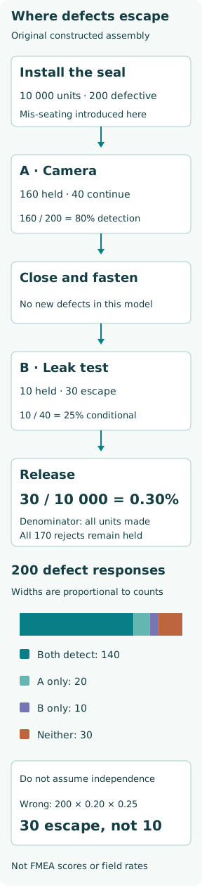
Use a constructed cohort of 10 000 assemblies with exactly 200 seal-seating defects introduced before A. Stipulate the joint responses of both checks to those same 200 defects: 140 are detected by both A and B; 20 by A only; 10 by B only; 30 by neither. These four mutually exclusive groups sum to 200. A detects 160/200 = 80%; B considered over the entire defect cohort detects 150/200 = 75%. The numbers are invented teaching inputs, not factory measurements.
Joint responses would need separate characterization if the real route removes A rejects before B. They cannot be reconstructed from two independent headline pass-rate reports. In a characterization exercise, controlled specimens can be tracked through both checks before their final disposition, provided the evaluation itself does not change the defects. In normal sequential production, the 160 A rejects are held; only the 40 A-surviving defects reach B.
Use conditional escape counts and name the denominator
Of those 40 survivors, B detects only the 10 in the B-only group. Its detection fraction on that selected population is 10/40 = 25%, not the marginal 75%. The escape count is therefore 200 × (40/200) × (30/40) = 30. Equivalently, the unique detected count is 160 + 150 − 140 = 170, leaving 200 − 170 = 30. Both routes give 85% combined detection of the original defects.
Multiplying the marginal miss fractions would give 200 × 0.20 × 0.25 = 10, an unjustified independence calculation. The correct escape fraction per produced unit is 30/10 000 = 0.30%. If all 9800 nondefective assemblies pass, no defects are added later, and all 170 rejects remain held, the released quantity is 9830 and the defective fraction among released units is 30/9830 ≈ 0.305%. These are different denominators. None of these fractions is an FMEA detection rating or an in-service failure probability.
Compare prevention with inspection using an explicit assumption
For a separate comparison, suppose a revised insertion process produces 40 rather than 200 defective assemblies per 10 000 units. Hold the four defect/inspection response proportions fixed only for this scenario: both detect 28, A only 4, B only 2, neither 6. The introduction fraction becomes 0.40%, and the escape count becomes 40 × 0.15 = 6, or 0.06% of production. That is an 80% reduction in the escape count with unchanged 85% combined detection.
This arithmetic illustrates where prevention acts; it does not predict a guide’s performance. A process change may preferentially eliminate easy-to-detect defects and leave a harder residual population. Then the previous response proportions do not transfer. Compare actual pre- and post-change defect mechanisms, production conditions and detector responses before estimating benefit. Raising a test’s sensitivity also requires checking false rejection and the resulting rework burden, which the baseline calculation excludes.
Turn the PFMEA row into a release and reaction rule
For this assembly, the control plan should connect the seating characteristic to camera A’s approved setup and the sealing characteristic to test B’s approved procedure. Identify the unit or lot, applicable recipe, evaluation method, inspection frequency, acceptance criterion, record and responsible role. Preserve the link to the exact PFMEA mode and process step. An undefined “100% check” says how many units are presented, not how reliably the defect is detected.
Specify the response to a failed check or an unavailable control: hold the affected material, establish the last demonstrably valid inspection state, assess the suspect production window, and authorize disposition through the defined quality process. A pack-station release check must reject missing, mismatched or stale test records. Reworked units need a defined return point and applicable repeat checks. These routes matter because a detected defect returned to the release stream can escape even when the detector itself worked.
Validate the complete path, including bypass and restart
A meaningful challenge set covers the relevant defect sizes, locations, materials and surface conditions, including cases near the acceptance boundary. It also covers known-good assemblies to expose false rejection. Record ground truth, specimen identity, equipment and recipe versions, production speed, observed decision, physical segregation and the release outcome. A test signal that lights a reject lamp is incomplete evidence if the rejected assembly can still be packed.
AIAG’s public guidance links error-proofing checks, rework and shutdown recovery to the control plan and PFMEA. Test restart, blocked reject chutes, authorized bypass expiry, mixed carriers and rework re-entry where relevant. NIST distinguishes acceptance sampling’s lot-disposition purpose from estimating lot quality. A sampled release decision is not per-unit detection, and a small successful challenge set does not establish zero escape probability across every production condition.
Keep priorities, action closure and production evidence connected
The AIAG & VDA FMEA approach introduced Action Priority in place of RPN. Use the method and rating definitions applicable to the project, rather than mixing tables or inventing a universal pass threshold. Ordinal severity, occurrence and detection ratings are not probabilities to multiply into an outgoing defect rate. The constructed counts above supplement the reasoning; they do not replace the applicable risk-prioritization method.
Close an action only after the changed fixture, inspection or release rule is implemented and its effect verified against the identified failure path. Keep the owner, due date, evidence reference and residual limitations visible. Review affected rows when the seal supplier, material, insertion tool, lighting, recipe, cycle time or rework route changes, and when returns reveal a missed mechanism. The practical result is a traceable answer to three questions: where the defect is created, what stops its progress, and what evidence shows that the stop works.