Knowledge / Machinery and energy
Boiler-furnace combustion safety: pre-purge, flame failure and fuel shutoff
Understand why airflow proving, flame supervision and fuel isolation are separate functions, using bounded dilution and response-chain examples rather than universal burner settings.
On this page
A furnace can contain unburned fuel after failed ignition, flame loss or leakage while stopped. Introducing an ignition source into that inventory can cause a rapid combustion event. Combustion safety therefore depends on several distinct functions: removing residual combustibles, proving suitable conditions before admitting fuel, detecting the intended flame and stopping fuel when the required conditions are lost.
A sequence is a set of physical conditions, not just a timer
A fan command does not prove airflow, an ignition command does not prove a flame, and a fuel-valve de-energization command does not prove that fuel has stopped. Each command needs the evidence appropriate to the physical function. A burner sequence links those conditions so that a later step cannot simply assume an earlier hazard has disappeared.
Siemens describes a generic sequence with pre-purge, ignition verification and continuous safety monitoring. Its industrial application references are not automatically the approval basis for a particular marine boiler. The installed burner, fuel, furnace geometry and applicable approval determine the actual interlocks, timings, restart policy and tests. The examples below are explanatory models, not substitute settings.
Pre-purge needs a verified flow path and meaningful airflow
Purging replaces or dilutes a potentially combustible atmosphere in the furnace and relevant flue passages. The air must travel through the intended volume. A running fan with an obstructed path, an incorrect damper position or a failed proving signal may not provide the required sweep. Measuring or proving one condition should not be treated as proof of every other condition.
The purge logic must account for the installation’s required permissives and what happens if they disappear during the interval. The question is whether the approved purge requirement has actually been fulfilled, not whether a clock has advanced. Continuing fuel ingress can defeat an otherwise adequate air sweep, which is why fuel isolation belongs in the same safety argument.
Worked example: the ideal well-mixed dilution equation
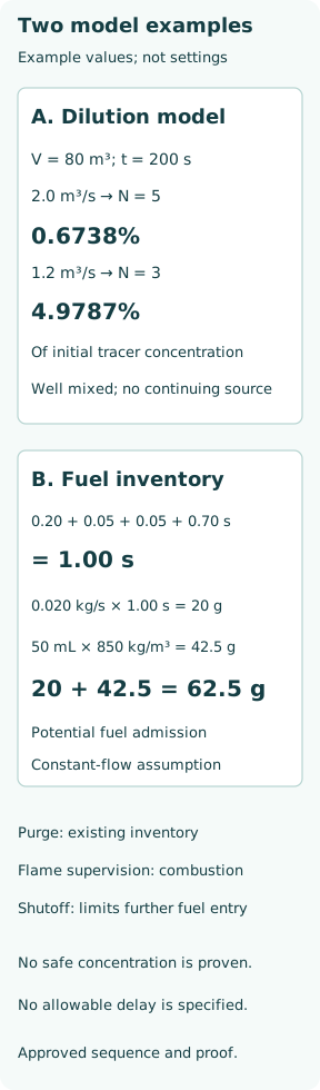
Consider an invented effective volume V = 80 m³, clean-air flow Q = 2.0 m³/s at the chamber conditions, constant density, complete mixing and no continuing contaminant source. Let C be a dilute tracer concentration and C0 its initial value. The balance V dC/dt = −QC gives C/C0 = exp(−Qt/V). Define N =Qt/V as the number of nominal volume exchanges.
For a chosen illustrative N = 5, the required model time is t =NV/Q = 200 s. The remaining fraction is e⁻⁵ = 0.006738, or 0.6738% of the initial concentration. This is a fraction of C0, not a fuel volume percentage. It does not establish that the furnace is below a flammability limit, because neither the real initial inventory nor a fuel-specific safe criterion has been established.
Why the same timer can represent a different purge
If actual airflow falls to 1.2 m³/s but the timer still runs 200 s, N becomes 1.2 ×200/80 = 3. The ideal remaining fraction is e⁻³ = 0.049787, or 4.9787% of the initial concentration. It is about 7.389 times the residual predicted for five exchanges. The timer has not changed; the physical dilution has.
Real furnaces need not behave as perfectly mixed tanks. Short-circuit flow, stagnant regions, liquid-fuel films, evaporation, stratification and ongoing leakage can invalidate this model. Ideal displacement flow would follow a different model too. Thus neither five exchanges nor 200 seconds is proposed as a generally acceptable purge. The calculation explains why verified flow, correct effective volume and an approved sequence matter.
Flame supervision must recognize the intended flame at the right time
A flame signal is meaningful only with the detector type, viewing geometry and sequence phase understood. Pilot-flame evidence must not be confused with successful main-flame establishment. A dirty optical path can reduce a genuine signal; unintended light or another flame can create a misleading one. Detector self-checking and discrimination requirements depend on the approved arrangement.
Fireye’s M4RT1 example prevents fuel-valve energization if flame is detected before start or during purge. That illustrates an important principle: a signal that is desirable during firing can be a fault in another phase. It does not prescribe this particular controller for marine use or make all burner restart policies identical.
Fuel shutoff is a response chain with real travel time
After an unsafe condition occurs, sensing, safety logic, output switching and physical valve movement take time. The total must be evaluated from the event to effective fuel isolation, using the approved component definitions. Some specified response times already include several elements; adding them again would double-count. A control-valve position indication is not automatically a safety shutoff-valve closure or tightness proof.
Fireye lists valve proving as a separate burner-management capability. Position, command status and leakage testing answer different questions. A closed-position switch can confirm an actuator position without establishing a leak-tight seat, while a flame detector cannot prove that no fuel leaks during a stopped period.
Worked example: account for fuel admitted after flame loss
For a separate illustrative oil-fuel inventory, assume non-overlapping delays of 0.20 s detector recognition, 0.05 s logic, 0.05 s output switching and 0.70 s valve travel. Their sum is 1.00 s. These invented values are not permitted response times. If fuel flow is conservatively held at 0.020 kg/s throughout that interval, the admitted mass is 0.020 kg, or 20 g.
Now assume a further 50 mL downstream of the isolation point could enter the burner, with density 850 kg/m³. Its mass is 0.000050 ×850 = 0.0425 kg. The combined illustrative potentially admitted inventory is 0.0625 kg, or 62.5 g. Actual closure flow should be integrated over time and actual downstream release established from the design. This mass is not an explosion-pressure prediction, an acceptable quantity or a reason to lengthen any delay.
A lockout needs cause resolution, not repeated ignition attempts
Siemens’ LFL1 documentation separates checks for failed ignition, flame loss, false light and air-proving failure. That separation helps identify what failed, rather than treating every stop as a nuisance alarm. The approved response may differ between startup and running conditions and between specific controllers; a generic automatic retry rule is inappropriate.
Repeated resets can introduce more unburned fuel when the underlying fault persists. An operator should follow the installed system’s fault procedure, preserve event evidence and involve qualified service personnel where required. Protective signals must not be bypassed to make an otherwise blocked sequence advance. Functional tests also need an approved method and safe plant state; this article is not a live-test script.
Verify the whole chain and keep the boundaries clear
Commissioning and periodic proof should address the actual safety chain: sensing, wiring, logic, outputs, physical isolation and the required reset/restart behaviour. Record configuration, timing definitions, calibrated evidence and valve condition. A successful screen simulation may prove software logic without proving a sticking physical valve; a moving valve does not prove correct flame discrimination.
Boiler water-level protection, pressure protection and combustion control interact with the burner but are separate functions. This article concerns unburned-fuel accumulation and ignition control. Its central lesson is that purge removes an existing inventory, flame supervision detects a combustion state and shutoff limits further fuel entry. One of those functions cannot stand in for the other two.