Knowledge / Machinery and energy
Controllable-pitch propellers: pitch demand, hydraulic movement and feedback
Follow the command, oil and position paths of a CPP, calculate a simplified pitch change, and distinguish a correct display from a correct blade position.
On this page
A controllable-pitch propeller (CPP) changes the angular position of its blades while the shaft can continue rotating in the same direction. This lets the propulsion system change thrust without treating every ahead-to-astern order as a shaft reversal. The engineering question is whether an accepted pitch demand produces the intended physical blade position, at the required rate and within the available hydraulic force. Understanding that question requires three separate paths: command, oil power and feedback.
What exactly does “pitch” describe?
A blade rotates about its own spindle in the hub. That rotation changes the local geometric pitch of the blade sections. An indicated percentage, a blade angle in degrees and a pitch-to-diameter ratio are different quantities; a display labelled “50%” cannot be inserted into a blade-angle equation without its calibration. In the discussion below, β is a defined blade-angle coordinate, not a universal bridge-display scale.
Changing pitch changes the angle at which rotating blades meet the incoming water. The resulting thrust also depends on shaft speed, vessel speed, wake and blade geometry. Zero geometric pitch, the maker’s indicated zero and the condition of zero net thrust need not coincide. A vessel with rotating blades can therefore still experience thrust or torque near an indicated neutral setting. Feathering is a separate configuration: SCHOTTEL describes it as an optional extension beyond the normal adjustment range. It must not be inferred from the presence of a CPP alone.
Trace the oil route without assuming one arrangement
A representative hydraulic CPP uses a power pack or gearbox-driven supply, control valves, an oil distribution interface, passages through the rotating shaft and a double-acting pitch actuator. In a hub-actuated arrangement, axial piston movement is converted into blade-spindle rotation by the hub mechanism. The opposite actuator chamber must discharge as the supplied chamber fills. The exact linkage, actuator location and pressure-holding arrangement are design-specific. Wärtsilä’s hub description contrasts a push-pull-rod arrangement with a servo cylinder inside the hub.
Kongsberg distinguishes a distribution box at the forward end of the reduction gearbox from an arrangement carried on a separate shaft. Wärtsilä also describes different oil-distribution and pressure-supply configurations. These examples establish why the approved oil diagram matters. “Oil pressure normal” at a supply gauge does not establish the pressure difference across the actuator after valve, passage and return losses. The return path is part of the power circuit, not merely a drain.
A command becomes motion through a closed loop
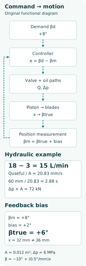
Define the demanded angle as βd and the measured feedback as βm. The controller acts on their difference e = βd − βm, subject to the selected control station, pitch limits and rate limits. A directional or proportional valve then meters oil. The piston moves, the hub linkage rotates the blades, and feedback reduces the error. Near the target, the system reduces the movement command and holds position according to its particular valve and locking arrangement.
The demand may intentionally be modified before it reaches the position loop. Engine-load limiting, an approved combinator schedule or a pitch-rate restriction can delay a large bridge order. A slow response is therefore not automatically a hydraulic fault. Compare the original bridge order, accepted internal demand and measured position on the same time axis. A display that merely repeats the accepted demand provides no independent evidence of motion.
Force and speed answer different questions
For an ideal equal-area actuator, F = Δp A and v = Quseful/A. Here F is hydraulic force in newtons, Δp is chamber pressure difference in pascals, A is effective piston area in square metres, v is piston speed in metres per second and Quseful is the volume flow actually causing displacement in cubic metres per second. Hydraulic power entering that simplified pressure boundary is Δp Q. Pressure enables force; useful flow sets the ideal movement rate.
A real unequal-area piston requires F = p1 A1 − p2 A2 on a consistent pressure reference. Seal friction, blade spindle friction and hydrodynamic blade-turning moments consume available force. The hub’s local transmission ratio converts actuator force into blade torque and piston travel into angle, and that ratio may vary through the stroke. A high-pressure indication alongside little movement is compatible with a heavy load or restriction. Increasing pressure is not a general remedy for missing flow or a faulty position signal.
Worked example: from litres per minute to blade movement
Consider an invented equal-area teaching actuator with A = 0.012 m², gross delivery 18 L/min, internal leakage 3 L/min, chamber differential 6 MPa and required travel 60 mm. Assume constant flow and pressure, incompressible oil, no acceleration interval and enough force to overcome the load. These are illustrative inputs, not data or settings for a commercial CPP.
Useful flow is 18 − 3 = 15 L/min = 0.00025 m³/s. Piston speed is 0.00025/0.012 = 0.02083 m/s, or 20.83 mm/s. Travel time is 0.060/0.02083 = 2.88 s. Ideal hydraulic force is 6,000,000 × 0.012 = 72,000 N = 72 kN. Gross hydraulic input at the stated pressure differential is 1.80 kW; 0.30 kW is dissipated by the stipulated leakage path, leaving 1.50 kW for ideal piston work. Pump input power would be greater once other losses are included.
Now assume, solely over this teaching stroke, a linear mapping from β = −10° at x = 0 mm to β = +20° at x = 60 mm. Then β = −10° + (0.5°/mm)x. A demand of +8° corresponds to x = 36 mm. This mapping is an assumption that must be replaced by the maker’s kinematic curve in real analysis; it is not a generic CPP calibration.
Why a stable feedback error can be more misleading than a lag
Suppose the indicated feedback has a +2° bias: βm = βtrue + 2°. When a simple position loop settles at βm = βd = +8°, the true angle is +6°, not +8°. With the teaching geometry, the piston stops at 32 mm instead of 36 mm. The controller sees zero error while the physical system retains a 2° position error. Raising controller gain cannot remove a bias in the measurement it trusts.
Feedback can be taken from a linkage, a translating rod or another approved measuring arrangement. Its location determines which failures it can reveal. A sensor upstream of a loose mechanical connection can report movement without proving that every blade followed. Conversely, a frozen display is not proof that the blades remained still. An independent position reference and the installed mechanical relationship are needed to resolve this ambiguity safely. As a concrete example, Kongsberg’s CP-A datasheet locates pitch feedback within its oil-distribution arrangement; it does not imply direct sensing on each blade.
Separate lag, deadband, drift and saturation
Lag is a delayed response to a change; deadband is a finite demand change that produces no commanded or observable movement; drift is changing position with nominally steady demand; saturation is reaching a command, flow, pressure or travel limit. These behaviours can coexist. For example, warm low-viscosity oil can increase leakage while a rate limiter independently constrains demand. The shape of the response matters more than one final reading.
For a controlled test record the accepted demand, feedback, independent reference where available, shaft speed, hydraulic pressures at identified locations, oil temperature and active limits. Compare ahead-going and astern-going travel at the same conditions, because linkage loads, areas and friction can differ. Do not diagnose a failed pump solely from slow movement, or condemn a sensor solely because thrust differs from expectation. Thrust is a hydrodynamic outcome; pitch is a mechanical position.
Loss of power does not have one universal pitch outcome
A CPP may include non-return, counterbalance or other holding arrangements, standby pumps and alternative control provisions. Which pitch is retained, how long it can be retained and whether movement remains possible after a failure depend on the installed design and the failure location. Neither “it goes to zero” nor “it always stays where it was” is a safe general rule. Leaks, loss of feedback and loss of supply are different failure cases.
The useful engineering check follows a specific failure boundary: what energy remains, which chamber paths remain contained, which control station has authority and what physical position can still be confirmed? Maintenance can leave stored hydraulic energy or permit unintended blade movement. Tests, isolation and recovery must follow the vessel’s approved procedure rather than improvised valve changes.
What constitutes convincing evidence?
A useful acceptance record connects demand, actual movement and operating conditions. It demonstrates direction, end positions, intermediate calibration, response rate, position holding and the specified alarms or fallback modes using an approved test plan. Agreement between two displays fed by the same transducer is one measurement shown twice, not two independent confirmations.
The central lesson is to keep three statements separate: a pitch order was accepted; the actuator moved; the blades reached the intended position. Each needs its own evidence. Hydraulic arithmetic makes that chain understandable, but the actual geometry, approved limits and installed feedback path decide whether the result is correct.