Knowledge / Machinery and energy
Fire dampers and doors: from a close command to compartment integrity
Separate closure commands, achieved movement, leakage paths and tested boundary performance through an original parallel-conduction example.
On this page
A close command is only the beginning of a fire-boundary claim. The blade or door leaf must reach its intended position, the installed assembly must preserve its approved construction, and the surrounding division must remain continuous. A simple heat-path calculation explains why a closed-looking boundary can still have a physically important weakness.
Name the physical function being claimed
A fire damper interrupts a ventilation path; a fire door closes an access opening in a division. Their required functions depend on the approved construction and application. “Closed” describes a position or state. It does not, by itself, state a tested fire-resistance classification, smoke-leakage performance or gas-tightness.
A boundary review should therefore start with a precise claim: which opening, which approved assembly and which function under which conditions? The distinction matters for CO2 retention as well as fire containment. A fire-rated assembly must not automatically be assumed gas-tight, and adding an unapproved seal is not a justified way to bridge that gap.
Trace command, movement and contact
A command can be issued without power reaching an actuator. An actuator can move while a damaged linkage fails to move the blade. A blade can reach an indicated position while debris or distortion prevents the intended contact. These are different physical failures and require observations at the relevant parts of the mechanism.
Historical MCA MSIS12 chapter 11 separates door closing and latching from damper indication and surrounding insulation details. It illustrates why a local position observation has a limited scope. The actual inspection and test method must follow the applicable approved arrangement, rather than a generic instruction to force or adjust the mechanism.
Follow the whole installed boundary
A door leaf sits within a frame attached to a supporting division. A damper is associated with a duct, coaming or spigot, insulation and its connection to the division. Inspecting only the moving item misses the interfaces through which heat, flame or gas may bypass it. The boundary is a connected construction, not a collection of independent certificates.
The 2010 FTP Code, part 3 and its damper appendix, evaluates defined specimens and distinguishes integrity from insulation performance. These are test claims with prescribed conditions. A successful closing indication at ordinary temperature is useful functional evidence, but it cannot reproduce the assembly’s behavior during a fire test.
Define an original thermal-bridge example
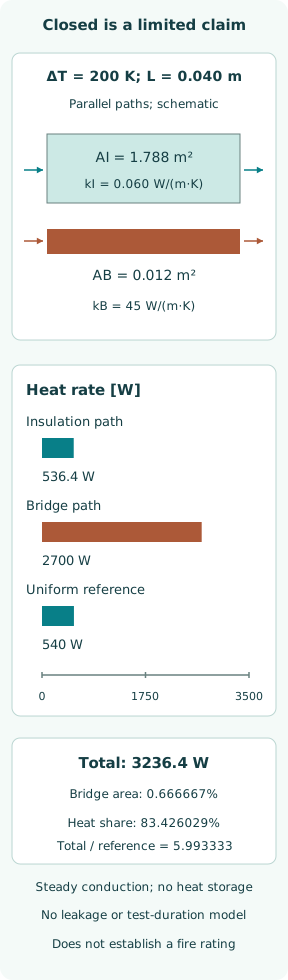
Consider a fictional fully closed planar panel of area 1.800 m² and thickness L = 0.040 m. Its low-conductivity material has assigned kI = 0.060 W/(m·K). A separate through-thickness bridge occupies AB = 0.012 m² with assigned kB = 45 W/(m·K). The remaining insulation area is AI = 1.788 m².
Prescribe a constant temperature difference ΔT = 200 K between both faces. Treat each path as one-dimensional, steady conduction with uniform properties and no lateral transfer. Ignore surface convection, radiation, contact resistance and heat storage. These artificial face conditions isolate parallel heat paths; they are not a furnace exposure, a real door design or a material-selection recommendation.
Calculate the parallel heat paths
Conductance is G = kA/L in W/K, and heat rate is GΔT. The insulation path gives GI = 2.682 W/K and 536.4 W. The bridge gives GB = 13.500 W/K and 2,700 W. In parallel, conductances add: Gtotal = 16.182 W/K and total heat rate = 3,236.4 W.
A uniform panel of the same total area and low-conductivity material would give 2.700 W/K and 540 W. The bridge occupies only 0.666667% of the area but carries 83.426029% of the modeled heat. The total is 5.993333 times the uniform reference. None of these ratios depends on a closure switch changing state.
Interpret the result within its thermal assumptions
The example demonstrates how a small parallel path can dominate a simplified steady heat balance. It does not show how long a real unexposed face takes to heat, because the model contains no heat capacity. It also does not predict thermal distortion, opening gaps or degradation of insulation as temperature rises.
Most importantly, the 200 K difference is an imposed face-to-face input, not a measured temperature rise at a specified test location. The calculated watts therefore cannot be converted into a fire-rating duration. An actual transient assembly analysis would need temperature-dependent properties, the exposure, surface exchange and the construction geometry, with appropriate validation.
A leakage path is a different physical problem
Even if the thermal path were known, leakage through a gap would require a separate pressure-and-flow description. The same visible gap may pass different flows under different pressure differences. Flow direction can change with ventilation and buoyancy. A closed limit switch does not measure that gap’s effective flow area or the gas transferred through it.
The worked panel contains no open gap and computes no leakage. This is deliberate: insulation weakness and integrity failure should not be conflated. A real assembly can need evidence for both, according to its approval. The choice of seal, permitted clearances and acceptance method must come from that basis, not from the artificial conduction example.
Product classification and compartment continuity differ
A product can retain a particular test classification while the installed division around it is damaged. Conversely, a local interface defect can implicate the assembled boundary. Those statements need careful location and construction evidence. The practical question is what path has been opened or changed, and what approved function that affects.
MCA UK21/F008 distinguishes a B-class supporting-bulkhead joint failure away from the doorframe from failure of the door construction. That specific interpretation does not make the failed surrounding boundary acceptable. It illustrates why the component label and the condition of the complete compartment should be recorded separately.
Functional testing must preserve the approval basis
A planned functional test can establish commanded movement and the required mechanical response under its stated conditions. A representative observation should identify the actual blade or leaf, relevant contacts, indication source and any obstruction. A repeated remote indication derived from the same switch is not an independent view of the whole assembly.
Repairs and modifications must preserve the applicable approved configuration. Extra insulation can obstruct a linkage; removing insulation for access can create a thermal path; an improvised seal can interfere with closure. The useful record includes the changed feature, its disposition and restoration evidence. It should never treat an altered assembly as equivalent merely because it still moves.
State exactly what each piece of evidence proves
A command log proves that a command was recorded. A position check supports a position claim. An approved fire-test report supports a specified construction and classification within its scope. An as-installed examination connects that construction to the actual ship. These pieces reinforce one another, but they are not interchangeable.
The original calculation adds one physical warning: a small unrepresented heat path can dominate a simplified boundary balance while the panel remains fully closed. No fire-rating or gas-tightness verdict follows from it. A sound compartment-integrity conclusion must join the mechanical, thermal, leakage and installation evidence relevant to the actual approved function.
Sources
- MCA MSIS12 chapter 11: Structural Fire Protection. Revision 1.01; historical survey instructions — 11.10.6–11.10.7; 11.13.4–11.13.6
- IMO MSC.307(88): International Code for Application of Fire Test Procedures, 2010. Adopted 3 December 2010; original resolution — Annex 1 part 3; appendix 2 A.II; part 4
- MCA UK21/F008: Fire tests for B-class doors. Published 19 July 2023; current official recommendation page inspected — Recommendation on supporting bulkheads and ceilings with fittings