Knowledge / Machinery and energy
Generator synchronizing: phase angle, slip frequency and breaker closing delay
Predict the phase angle at contact closure, distinguish voltage/frequency/phase matching, and see how breaker timing and measurement uncertainty change synchronization.
On this page
Two generators can both display approximately 50 Hz and still be unsuitable for immediate parallel connection. Their voltage magnitudes, phase sequence and instantaneous relative phase must be compatible, and the circuit breaker takes time to close. The decisive angle is the angle when its main contacts make, not merely the angle when a close command is sent. This article develops that timing model without prescribing settings or a live switching procedure.
Matching has several independent conditions
Voltage magnitude, frequency and phase angle describe different properties of an AC waveform. Equal rms voltage does not imply equal phase; equal frequency does not imply that two voltage phasors are aligned. Phase sequence must also correspond across a three-phase connection. Matching one measured phase cannot correct a reversed sequence or a misidentified voltage-transformer circuit.
DEIF’s synchronizer description explicitly includes voltage difference, slip frequency and phase angle within its closing criteria. The permissible values must come from the installed generator, switchgear and approved protection/control design. A generic percentage or degree window is not an interchangeable setting across vessels. A synchronism-check function provides a permissive under its configured conditions; it is not proof that every measurement connection and operating mode is correct.
Phase angle moves at the slip frequency
Define δ = θgenerator − θbus in electrical degrees, so negative δ means the incoming generator voltage lags the bus. Define slip Δf = fgenerator − fbus in hertz. For approximately constant frequencies, dδ/dt = 360 Δf degrees per second. A positive slip makes δ increase: a lagging incoming phasor moves toward coincidence, passes it and becomes leading.
For nonzero constant slip, successive coincidences are separated by 1/|Δf| seconds. If Δf is exactly zero, an existing angle error remains fixed unless the control system changes the relative phase. Therefore “the frequency meters agree” is not enough. A synchroscope indicates relative phase movement; its direction and labelling must be interpreted for the installed instrument rather than remembered from an unrelated display.
The breaker adds a time interval, not an instantaneous event
A command passes through controller outputs and any interposing devices before the closing mechanism operates and the main contacts make. The relevant prediction delay must match the definition used by the synchronizer. ABB’s synchronism-check documentation defines a total closing delay that includes output-contact delay. Adding the same relay delay again would overcompensate; omitting it would undercompensate.
For constant slip, δcontact = δcommand + 360 Δf tc, where tc is the modelled command-to-contact interval. To target zero angle in this sign convention, δcommand = −360 Δf tc. This is a signed relationship. A positive slip requires a lagging command angle in this example; “advance by three degrees” without a sign convention can be ambiguous. DEIF’s dynamic-synchronization section uses the slip and breaker response time to anticipate coincidence.
Worked example: command first, contacts later
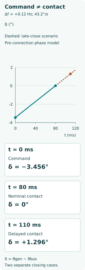
Let the bus be 50.00 Hz and the incoming generator 50.12 Hz. Assume constant slip and a total closing interval of 80 ms = 0.080 s. These are invented teaching values, not recommended synchronizing limits. Slip is +0.12 Hz and angle rate is 360 × 0.12 = 43.2°/s. A full relative revolution takes 1/0.12 = 8.33 s.
The command angle for nominal zero-angle contact is −43.2 × 0.080 = −3.456°. At command time the generator therefore lags by 3.456°. After 80 ms it has gained 3.456° and nominally reaches zero. Sending the command at zero angle instead would make the contacts close at +3.456° in the same constant-slip model. This distinction is the entire reason for timing compensation.
Now hold the command angle fixed but let the actual closing time become 110 ms. The contact angle becomes −3.456 + 43.2 × 0.110 = +1.296°. A 30 ms change in mechanism/control delay has shifted the closure angle even though the frequency and voltage indications are unchanged. Actual breaker timing must therefore be measured and maintained, not inferred solely from a nominal catalogue value.
Uncertainty belongs in the prediction
In the example, a timing error of ±20 ms alone contributes ±43.2 × 0.020 = ±0.864°. A slip-estimation error of ±0.01 Hz over the nominal 0.080 s contributes ±360 × 0.01 × 0.080 = ±0.288°. Their first-order worst-case sum is ±1.152°. Keeping the product term in 360 Δf tc adds a bound of 360 × 0.01 × 0.020 = 0.072°, giving a conservative total bound of 1.224° for those two errors together.
This is a bounded-error illustration, not a statistical confidence interval or an acceptance limit. Phase-measurement error, sampling latency, contact pole scatter and changing frequency are not included. If the slip changes at a constant rate a, the extra predicted phase change is 180 a tc². For a = 0.2 Hz/s and tc = 0.080 s it is 0.2304°. A controller may use more sophisticated prediction, but its model and measurement age still need to match the physical process.
Equal voltage magnitude does not remove the closing stress
For a simplified pair of equal phase-voltage phasors of rms magnitude E separated by angle δ, the voltage across the open connection has magnitude |ΔE| = 2E |sin(δ/2)|. At E = 230 V and δ = 10°, this is approximately 40.09 V, despite both voltmeters reading 230 V. With a purely illustrative total reactance of 0.15 Ω, the corresponding phasor-current estimate is 267 A.
This small calculation is not a generator fault-current or shaft-stress study. It omits resistance, subtransient behaviour, dc offset, saturation and electromechanical dynamics. It explains the mechanism: the connection equalizes two sources that are not at the same instantaneous voltage, potentially creating electrical and torque transients. Real consequences require the actual network and machine model; no safe closing angle can be derived from the arbitrary 0.15 Ω example.
Dynamic and near-zero-slip approaches solve different timing problems
Dynamic synchronization allows a controlled slip and predicts the upcoming coincidence. Near-zero-slip or static synchronization actively brings the phase error close to zero while keeping frequencies nearly equal. DEIF describes both approaches and their control differences. Reducing slip slows phase movement but does not automatically eliminate a pre-existing phase offset.
Once the breaker closes, the machine joins the common electrical system and the controls must transition to the intended load-sharing mode. Prime-mover torque primarily affects active-power sharing; excitation primarily affects reactive-power sharing in the usual simplified model. A visually clean close is therefore only the start of successful paralleling. Incorrect post-close control can lead to poor sharing or reverse power even when the predicted contact angle was satisfactory.
Measurement routing can defeat correct arithmetic
A synchronizer must compare the voltages on the two sides of the breaker actually selected for closing. A wrong bus selection, reversed polarity, incorrect transformer phase compensation or stale remote signal can make a mathematically correct prediction refer to the wrong electrical condition. The measurement and command paths need consistent identity as well as consistent time.
SEL’s synchronizing paper discusses signal selection, latency and why a software-drawn synchroscope is unsuitable as a precise manual closing timer. Those issues are relevant even when the screen looks smooth. A permissive from the same wrongly selected voltage pair is not independent protection against that selection error. The design must address common failures and be verified against the actual switchboard topology.
Dead-bus closing is a separate case
An intentionally dead bus has no meaningful live-bus phase reference to follow. Energizing it uses a different approved permissive and coordination scheme, including a valid determination that the intended bus is dead and that competing sources will not close incompatibly. A missing voltage signal caused by a fuse or measurement fault must not be mistaken for proof of a dead bus.
Similarly, closing a bus-tie between two energized islands is synchronization of two systems, not simply confirmation that each island has acceptable voltage. Their relative angle and frequency can evolve while loads change. The installed logic and source controls determine the permissible action. These cases should not be “solved” by bypassing a blocking synch-check function.
A useful verification record follows command through contact
Record the selected source/bus, voltage magnitudes, phase sequence verification, measured slip and phase, close-command timestamp, actual contact event and the definition of the delay used in the calculation. Include instrument timing uncertainty and post-close active/reactive power behaviour. Auxiliary contacts may have an offset from main-contact touch; the test method must account for the particular indication used.
The key distinction is between permission to close, a close command and successful main-contact closure at the intended condition. An alarm or blocked close calls for the approved investigation path, not repeated unsupervised attempts. A sound synchronization assessment joins the waveform, the controller and the mechanical breaker on one time axis and checks what actually happened.