Knowledge / Machinery and energy
Multistage air compressors: intercooling, stage pressures and volumetric efficiency
Explain why cooling between stages changes compression work, derive an ideal pressure split, and calculate how clearance-gas re-expansion reduces fresh intake.
On this page
A multistage air compressor divides a large pressure rise among several compression steps and removes heat between them. Its benefit is not simply that each cylinder is smaller or that a final thermometer reads a lower temperature. Intercooling changes the gas volume entering the next stage, while stage pressure ratios affect temperature, work and fresh-air intake. These relationships can be understood with two distinct models: polytropic compression and clearance-gas re-expansion.
Follow pressure, temperature and mass separately
In a representative reciprocating arrangement, a first-stage cylinder compresses air, an intercooler removes heat, and a later cylinder continues compression. A separator removes condensate where provided; an aftercooler acts after the final stage. Atlas Copco’s two-stage explanation describes the larger first cylinder, interstage cooling and smaller second cylinder. The smaller downstream volume follows increased density, not disappearing air mass.
In steady operation with negligible leakage or extracted mass, stages pass approximately the same dry-air mass flow even though their actual volumetric flows differ greatly. Condensate separation changes the water carried downstream. Distinguish stage inlet pressure from discharge pressure and specify whether a stated pressure is absolute or gauge. Thermodynamic pressure ratios require absolute pressures.
Intercooling reduces the volume that the next stage compresses
For an ideal gas, specific volume is v = RT/p. Cooling at approximately fixed interstage pressure decreases v, so the next compression step begins with denser gas. In an ideal internally reversible model, compressor work depends on the integral of v dp. Reducing v over part of the pressure rise reduces work.
Atlas Copco’s multistage discussion identifies cooling between stages and equal pressure ratios as the ideal efficiency reference. Equal ratios require qualifications: equal inlet temperatures after cooling, comparable compression behaviour and negligible intermediate pressure loss. Different stage efficiencies, imperfect cooling, valve losses or design constraints can shift the best practical split. An installed interstage pressure is not a free setting to adjust to a textbook square root.
Write the polytropic model with its assumptions
For the teaching calculation, air is an ideal gas following pvⁿ = constant in each compression stage, with the same exponent n = 1.3. The stage temperature ratio is Tout/Tin = r^((n−1)/n), where r = pout/pin uses absolute pressure. The ideal polytropic specific work is w = [n/(n−1)]RTin[r^((n−1)/n) − 1]. With R in J/(kg·K), w is J/kg.
This is an internally reversible polytropic comparison, not an isentropic-efficiency calculation or measured electric input. Cylinder cooling is represented through the chosen exponent; mechanical friction, motor losses, valve pressure drops and leakage are omitted. Use kelvins for absolute temperatures. The same expression cannot be applied by substituting a Celsius inlet temperature.
Worked example: the geometric-mean pressure split
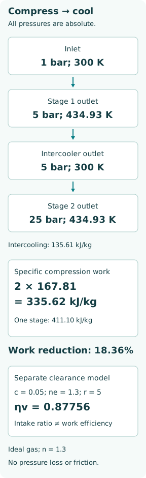
Take an invented two-stage system from p1 = 1 bar absolute to p3 = 25 bar absolute, with each stage inlet restored to 300 K by ideal intercooling. For equal inlet temperature and exponent, the minimum-work split is p2 = √(p1p3) = 5 bar absolute, so both stage ratios are 5. Their product is 25; pressure rises are not equal. A stated final pressure of 25 bar gauge would instead require a different absolute-pressure calculation.
Each stage reaches 300 × 5^(0.3/1.3) = 434.93 K and requires 167.81 kJ/kg using R = 287 J/(kg·K). The two-stage total is 335.62 kJ/kg. Under the same ideal polytropic exponent, a single stage across ratio 25 would reach 630.55 K and require 411.10 kJ/kg. Ideal intercooling therefore reduces this comparison’s work by 18.36%. These are model results, not commercial compressor performance or permissible discharge temperatures.
The minimum follows directly because r1r2 is fixed and work is proportional to r1^a + r2^a − 2, with a = (n−1)/n. For positive ratios, that sum is minimized when r1 = r2. The result ceases to be that simple when the two inlet temperatures or stage characteristics differ.
The intercooler has a real heat duty
Using an assumed cp = 1.005 kJ/(kg·K), cooling the first-stage discharge from 434.93 to 300 K removes approximately 135.61 kJ per kilogram of dry air. At a known mass flow, multiply by kg/s to obtain kW. This intercooler duty is separate from heat transferred during the polytropic cylinder process and from the final aftercooler duty.
If the second-stage inlet is 340 K instead of 300 K while the two pressure ratios remain 5, total ideal work rises to 358.00 kJ/kg. The same final pressure can therefore be reached with a changed power demand and higher second-stage temperature. A cooler’s outlet temperature, pressure drop and cooling-medium condition need to be evaluated together: stronger heat transfer accompanied by excessive restriction is not automatically a better whole-system result.
Clearance gas occupies part of the next suction stroke
At the end of discharge, some compressed gas remains in the cylinder’s clearance volume Vc. As the piston returns, that gas expands before cylinder pressure falls enough for fresh suction to begin. Let swept volume be Vs, clearance ratio c = Vc/Vs and re-expansion exponent ne. With ideal valves and no heating or leakage, volumetric efficiency is ηv = 1 + c − c r^(1/ne).
The expression follows by subtracting the re-expanded residual volume Vc r^(1/ne) from the full bottom-dead-centre volume Vs + Vc, then dividing fresh intake by Vs. It is a volumetric intake ratio, not motor efficiency or compression energy efficiency. Real suction heating, valve dynamics, leakage and pressure losses change the result. A mathematical negative value would mark the breakdown of the assumed intake cycle, not a physically negative delivered flow.
Worked intake example: swept flow is not delivered flow
Let c = 0.05, ne = 1.3 and stage ratio r = 5. Then ηv = 1.05 − 0.05 × 5^(1/1.3) = 0.87756, or 87.76%. With a first-stage swept-volume rate of 10.00 m³/min, ideal fresh intake is 8.7756 m³/min at the specified suction condition. At 1 bar absolute and 300 K, ideal air density is 100,000/(287 × 300) = 1.16144 kg/m³, giving 0.16987 kg/s.
Combining that mass flow with the earlier two-stage specific work gives 0.16987 × 335.62 = 57.01 kW of ideal polytropic compression power. Electric input would need additional losses. The stated 8.7756 m³/min is not automatically a standardized free-air-delivery rating; a published capacity must include its reference conditions and test method.
For comparison only, putting ratio 25 into the same clearance model gives ηv = 0.45529. That is not a proposed single-stage machine. It demonstrates why a large stage pressure ratio can severely reduce fresh intake in a reciprocating cylinder even before thermal and mechanical limits are considered.
Interstage readings are diagnostic evidence, not a diagnosis
An interstage pressure results from the mass-flow compatibility of adjacent stages and the intervening cooler and valves. A changed reading can be associated with suction restriction, valve leakage, altered cooling, leakage between stages or changed downstream demand. One pressure alone does not select the cause. Compare the whole pressure–temperature pattern at the same operating condition.
Sauer’s marine brochure cautions that calculated cylinder/valve compression temperatures are not the same as readings from ordinary compressor thermometers. Sensor location and thermal lag matter. A reassuring cooler-outlet reading cannot by itself exclude excessive upstream valve temperature. Record the location and meaning of each measurement before comparing it with a model.
Cooling and condensate handling are part of capacity
BAUER’s multistage equipment description treats intercooler, aftercooler and valve-head cooling together with condensate removal. A drained separator and an effective cooler support operation, but changing pressure components, drainage or protective devices is not an informal efficiency adjustment. Follow the installed maker’s inspection and isolation procedure; compressed volumes can retain hazardous energy after the motor stops.
The engineering result should connect required mass flow and final pressure to stage ratios, inlet temperatures, cylinder displacement, re-expansion losses and the actual cooling duty. Keep the three efficiency ideas separate: volumetric efficiency describes fresh intake, thermodynamic efficiency describes compression work, and mechanical/electrical efficiency connects that work to supplied power. Treating all three as one percentage hides why a compressor can reach pressure yet deliver too little air or consume too much power.