Knowledge / Machinery and energy
Shaft-system axial vibration: dynamic thrust, bearing stiffness and damping
Follow longitudinal excitation through the thrust-bearing support, calculate a bounded harmonic response, and distinguish displacement amplification from transmitted dynamic load.
On this page
A propulsion shaft can move along its own axis as well as twist or bend. Fluctuating propeller thrust and engine-related excitation act on an elastic system of shafting, machinery, thrust bearing and supporting structure. Near an axial natural frequency, a modest periodic force can produce a much larger motion or support load than a static calculation suggests.
Axial, torsional and radial vibration are different coordinates
Axial vibration is displacement parallel to the shaft axis. Torsional vibration is angular oscillation about that axis, while lateral vibration is transverse motion. Their excitation paths and stiffnesses differ, even though a real propulsion train can couple them. A satisfactory torsional assessment therefore does not independently establish acceptable axial response.
ABS treats longitudinal machinery/shafting vibration separately and models the associated masses and stiffnesses. The effective axial system includes more than the steel shaft alone. Thrust-bearing, engine-bedplate and hull-foundation flexibility can move natural frequencies and change the path by which dynamic loads reach the structure.
Mean thrust and alternating thrust play different roles
Mean propeller thrust establishes the loaded equilibrium. The alternating component excites vibration about that state. A propeller operating in a nonuniform wake can generate periodic forces related to shaft speed and blade passage, with additional harmonics. Engine excitation can contribute other orders and phases; the relevant excitation spectrum must be identified for the actual installation.
Wärtsilä describes thrust transfer from the shaft through tilting pads to the bearing housing. The dynamic support load need not equal the applied harmonic force instant by instant, because the intervening masses accelerate. Oil-film behaviour, pad loading and housing response also cannot be inferred from a mean thrust number alone.
A one-mode model exposes the main relationships
For an illustrative linear axial coordinate x about the loaded equilibrium, write m ẍ + c ẋ + kx =F0 sin(ωt). Here m is effective mass in kg, c damping in N·s/m, k effective axial stiffness in N/m and F0 the peak harmonic force in N. The foundation is fixed in this model. The undamped natural frequency is fn =√(k/m)/(2π).
The steady displacement amplitude is X =F0/√[(k −mω²)² +(cω)²]. Define damping ratio ζ =c/(2√km). This model omits multiple modes, nonlinear bearing contact, distributed shaft deformation and hull motion. Its coordinate is not automatically a bearing oil-film thickness or a measured collar clearance. It is a teaching approximation for one effective mode.
Worked example: frequency and excitation order
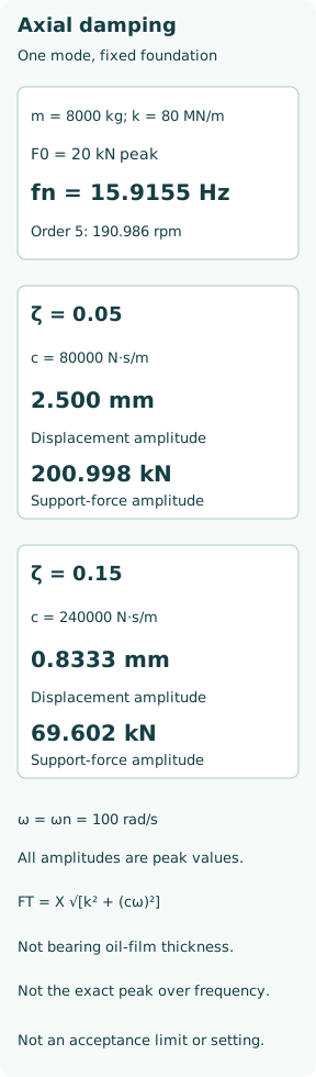
Choose effective mass 8000 kg, stiffness 80 MN/m and peak excitation 20 kN. Then ωn =√(80 ×10⁶/8000) = 100 rad/s and fn = 15.9155 Hz. The static deflection scale from the alternating-force amplitude is F0/k = 0.00025 m, or 0.250 mm; this is not yet the dynamic response.
For a stipulated fifth-order excitation, f = 5n/60 with shaft speed n in rpm. It crosses this natural frequency at n = 60 ×15.9155/5 = 190.986 rpm. The order refers to the shaft used in that equation; geared engine speed must not be substituted without its ratio. The crossing is an illustrative resonance location, not an authorized operating or barred-speed boundary.
At the natural frequency, damping controls amplification
First take ζ = 0.05. The corresponding damping is c = 2 ×0.05 ×√(80 ×10⁶ ×8000) = 80000 N·s/m. At ω =ωn, the elastic and inertial terms cancel, so X =F0/(cωn) = 20000/(80000 ×100) = 0.00250 m, or 2.500 mm. This is ten times the static force-deflection scale.
For a separate ζ = 0.15 case with the same mass, stiffness and force, c = 240000 N·s/m and X = 0.8333 mm at the same frequency. The response is one third of the first case. For these two stated damping ratios, the exact maximum-displacement frequency is slightly below the undamped natural frequency; these numbers compare response at ωn, not an exact search for each peak.
Transmitted load includes both elastic and damping forces
The support reaction in this model is kx +c ẋ. Its alternating amplitude is FT =X√[k² +(cω)²], because spring and viscous-damping force components are in quadrature for harmonic motion. At ωn, case A gives FT = 200.998 kN; case B gives 69.602 kN. Simply reporting kX alone would omit the damping-force component.
If mean support thrust is separately stipulated as 250 kN and the linear model remains valid, the ideal total reaction ranges from 49.002 to 450.998 kN in case A, and 180.398 to 319.602 kN in case B. These are model force ranges, not pad-load predictions or bearing acceptance values. If an assumed oscillation unloads a face, introduces clearance or transfers load between faces, the linear model must be replaced.
Changing stiffness moves the frequency rather than removing every risk
In a separate frequency-only comparison, increase effective stiffness 20% while keeping effective mass unchanged. Natural frequency rises by√1.20, from 15.9155 to 17.4346 Hz. Stiffening can move a resonance away from one excitation, but it can also move it toward another order or another operating speed. More stiffness is not an unconditional cure.
Real supports contain several compliances. Shaft axial stiffness, bearing oil-film behaviour, casing, bedplate and hull foundation can act in coupled paths. A local reinforcement does not necessarily increase the relevant modal stiffness by the same percentage as the reinforced part’s own stiffness. Mode shapes and effective masses should be recalculated after a material design change.
An axial damper is not a torsional damper by another name
The MAN project guide describes a crankshaft-mounted axial vibration damper and separate torsional-vibration equipment. That is a specific engine arrangement, illustrating distinct functions. Its damper location, monitoring and approved operating requirements cannot be transferred wholesale to every shaft system.
Damping can reduce resonant motion by dissipating energy, but it also carries dynamic force and may depend on temperature, fluid condition and frequency. A damper fault can change the response without changing mean propeller thrust. Any modification requires the engine/shaft-system design assessment; the example’s damping ratios are not settings to be adjusted on installed equipment.
Measure the relevant coordinate and phase
An axial displacement probe measures a different quantity from a casing accelerometer. Location, direction, bandwidth and reference point matter. Shaft-relative motion, absolute housing motion and inferred dynamic thrust should not be substituted for one another. Order tracking against a synchronized speed reference helps distinguish speed-related excitation from unrelated structural or auxiliary-machine frequencies.
Compare the measured speed/load trend with calculated mode shapes, forcing orders and damper condition. Use the applicable manufacturer and approval criteria for the actual measured quantity, including whether values are peak, peak-to-peak or RMS. The example uses peak harmonic amplitudes throughout. The core lesson is to assess the whole axial load path: mean thrust sets equilibrium, stiffness sets the frequency scale, and damping strongly changes the resonant displacement and transmitted load.