Knowledge / Machinery and energy
Waterjet propulsion: inlet flow, momentum balance and net thrust
Build a waterjet control volume, subtract incoming momentum from the jet force, and see why inlet velocity profiles and pump–nozzle matching matter.
On this page
A fast stream leaving a waterjet is visually persuasive, but its outgoing momentum is only half of the thrust account. Water entered the propulsion system with momentum already present relative to the moving vessel. Net thrust follows the change in momentum, together with the pressure and boundary forces belonging to the chosen control volume. Keeping that boundary explicit prevents gross jet force, pump power and useful propulsive power from being confused.
Follow the water through the machine
A typical flush-inlet waterjet takes water through a hull opening and duct, raises its total head in a pump, reduces swirl where a stator is fitted, and accelerates the flow through a nozzle. Steering and reversing devices redirect the outgoing stream. The machinery arrangement and permitted operating envelope belong to the particular product; HamiltonJet’s HJ designer manual is one manufacturer example, not a specification for all waterjets.
The inlet must supply the pump with an acceptable flow over the vessel’s speed and attitude range. An inlet lip, duct curvature or ingested hull boundary layer can make the velocity distribution uneven. A pump that performs well in a uniform-flow test can behave differently in that installed flow. The nozzle and inlet therefore cannot be treated as passive accessories added after pump selection.
Choose the moving reference frame and pressure boundary
For the elementary model, use a control volume attached to a steadily translating vessel. Define positive water velocity aft through the jet. Let Q be steady volume flow, ρ density, Vi the uniform inlet velocity and Vj the uniform outlet velocity, all measured relative to the vessel. Assume incompressible water, a straight axial outflow, negligible elevation change and a boundary at which the net gauge-pressure contribution has been removed or cancels.
The forward thrust magnitude in this ideal model is T = ρQ(Vj − Vi). The outgoing term ρQVj is often called gross momentum thrust; ρQVi is the incoming momentum term. If the chosen inlet/outlet stations have non-cancelling pressure forces, include them. Do not append only an outlet pressure correction to an arbitrary inlet plane and call the result universal net thrust. The control-volume surface, surrounding pressure and hull-force accounting must be consistent.
Why the inlet term must be subtracted
Imagine drawing the boundary around the whole water stream processed by the unit. During each second, the mass entering is already moving aft in the vessel-fixed frame. Only its increase in aft momentum supplies the corresponding forward reaction. Counting all outgoing momentum as new would credit the pump with momentum carried into the boundary by the incoming water.
This is also why a stationary bollard test and a vessel underway need separate conditions. In a simplified undisturbed upstream model Vi approaches zero at zero vessel speed, but the inlet duct itself still has substantial local velocity caused by suction. A local inlet-duct velocity cannot simply be substituted for far-upstream velocity while leaving the rest of the pressure and hull terms unchanged. The ITTC waterjet-validation report makes system boundaries and the distinction between momentum and energy flux central to its method.
Worked example: gross force is not net thrust
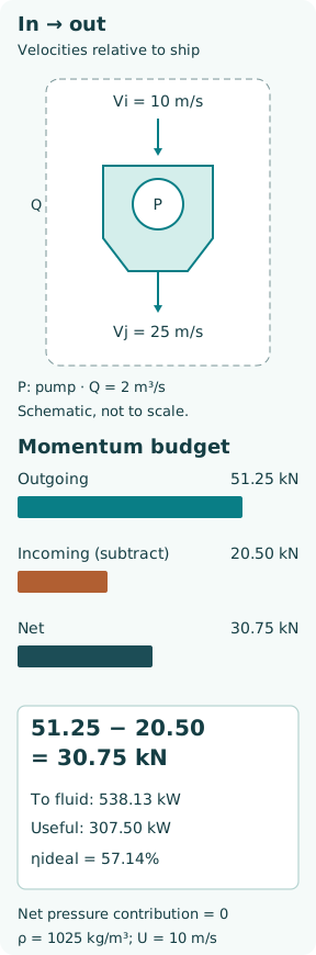
Take invented uniform-flow values: seawater density ρ = 1,025 kg/m³, Q = 2.00 m³/s, ship speed U = 10 m/s, Vi = U and Vj = 25 m/s. Use the ideal pressure assumptions above. Mass flow is ρQ = 2,050 kg/s. Outgoing momentum is 2,050 × 25 = 51,250 N; incoming momentum is 2,050 × 10 = 20,500 N. The net is 30,750 N = 30.75 kN.
Reporting 51.25 kN as the net thrust would overstate this example by 20.50 kN, or 66.7% relative to its actual modelled net value. Continuity also gives nozzle flow area Aj = Q/Vj = 0.080 m². It is the effective flow area, not automatically the external nozzle diameter or a pump-eye area. These inputs describe an ideal teaching system, not a selected commercial unit.
Momentum and energy lead to different useful quantities
The ideal rate of added fluid kinetic energy in this vessel-fixed model is Pfluid = ½ρQ(Vj² − Vi²). With the example values, Pfluid = 538,125 W = 538.13 kW. The useful rate of work against vessel resistance at U = 10 m/s is T U = 307.50 kW. Their ratio is 0.5714, equivalently 2U/(Vj + U) under the same ideal assumptions. The difference is associated with energy left in the accelerated stream, rather than useful vessel work.
If a hypothetical pump efficiency of 0.82 is the only additional loss, shaft power is 538.125/0.82 = 656.25 kW. Useful power divided by shaft power becomes 46.86%. Real inlet, nozzle, mechanical and installation losses need their own consistent accounting. ITTC’s performance procedure separates ideal, pump and ducting contributions; multiplying arbitrary efficiency labels with overlapping losses would count some losses twice.
At bollard condition, T U is zero because the vessel does not translate, although thrust and shaft power can both be substantial. A zero value of this particular propulsive-efficiency definition does not mean that the unit produces no useful manoeuvring force. State which performance measure answers the task: thrust, thrust per shaft power, speed–power performance or manoeuvring response.
A velocity average is not always a momentum average
For axial flow normal to a plane, volume flow is the area integral of u, while axial momentum flux is ρ times the area integral of u². Kinetic-energy flux involves ½ρ times the area integral of u³. Squaring an average is generally different from averaging the squares. That mathematical distinction matters when an inlet ingests a boundary layer or distorted stream.
As a separate teaching check, divide a 0.20 m² inlet plane into two equal 0.10 m² zones at 8 and 12 m/s. Q remains 0.10 × 8 + 0.10 × 12 = 2.00 m³/s and the area-mean velocity is 10 m/s. But inlet momentum is 1,025 × 0.10 × (8² + 12²) = 21,320 N, not 20,500 N. With the same uniform outlet momentum, the momentum difference is 29.93 kN, 0.82 kN below the uniform-inlet estimate.
For this two-zone plane the momentum correction factor is 1.04 and the kinetic-energy correction factor is 1.12. They are not interchangeable. The comparison isolates velocity-profile arithmetic while holding the other boundary assumptions fixed; it does not claim that an actual inlet can change profile without also changing pressure, losses and pump operating point.
The pump and nozzle determine the operating point together
At a specified shaft speed, a pump has a head–flow characteristic and efficiency/cavitation limits. The installed water path requires a total-head increase to overcome losses and provide the nozzle velocity. Their compatible operating point determines Q; flow is not an independent free setting merely because a motor speed is known.
Shrinking a nozzle area can increase outlet velocity for a given Q, but Q itself generally changes as the system head requirement rises. More jet speed therefore does not automatically mean more net thrust or better efficiency. Matching requires the pump map, inlet conditions, nozzle geometry and engine or motor envelope across the required speed range. ITTC distinguishes inlet-duct tests, pump-loop tests and whole-system tests because installed interaction is not captured by a uniform-inflow pump test alone.
Steering, reversing and degraded inflow change the balance
With a deflected jet, thrust is a vector. A simple axial projection uses the aft momentum component Vj cos θ only if the stream actually follows the assumed angle and other boundary forces are treated consistently. A reversing bucket redirects flow rather than reversing the pump. A near-neutral vessel force can coexist with substantial internal flow and power. It should not be read as proof that the machinery is unloaded.
Air ingestion, debris, disturbed inlet flow and cavitation can change flow, pressure rise and the pressure/momentum distribution together. For diagnosis, connect shaft speed and torque with available pressure, flow and vibration evidence. Do not explain a loss of thrust solely by one gauge or infer a safe operating point from the sound of the jet. Inspection, clearing and test manoeuvres must use the maker’s procedures and vessel’s safe operating arrangements.
A defensible result includes its boundary and uncertainty
Report inlet and outlet station definitions, reference frame, volume flow, velocity distributions or justified uniform approximations, pressure contributions, shaft power and the associated vessel condition. Keep waterjet net thrust distinct from bare-hull resistance and from the entire hull–waterjet interaction unless the adopted method explicitly relates them. A subtraction can be arithmetically correct and still use inconsistent boundaries.
The example’s main lesson is not a universal efficiency number. It is a repeatable sequence: define the control volume, determine what enters and leaves, account for pressure forces, calculate the momentum change, and then evaluate energy separately. That sequence explains both why the inlet term matters and why an attractive nozzle jet is not a complete performance measurement.