Knowledge / Shipyards and ship structures
Galvanic corrosion at dissimilar-metal joints: area ratio and electrical continuity
Trace the electrical and electrolyte paths at dissimilar-metal joints and use an original variable-current example to interpret cathode-to-anode area ratio.
On this page
A small anodic fitting attached to a large cathodic surface can face concentrated attack when an electrolyte completes the circuit. Yet area ratio alone does not specify the current or service life. The metals, exposed areas, electrical connections, solution paths and electrode reactions form one coupled system; changing one part can change the operating point of the whole cell.
Draw both sides of the circuit
Electrons travel through conductive metal connections, while ionic transport and electrode reactions complete the path through the electrolyte. The connection need not be a clean, visible joint between two immersed pieces. A remote metal support, bonding path or connected piping can maintain electrical continuity, and moisture trapped around the joint can provide the electrolyte bridge.
TWI describes the combination of dissimilar electrochemical behaviour, electrical contact and electrolyte exposure. A drawing that shows only the two alloy names misses the actual circuit. Mark where surfaces are wetted and which conductive routes remain in the installed assembly. Dry appearance during one inspection does not describe a joint repeatedly wetted by spray or condensation.
Use a galvanic series with its environment attached
A galvanic series describes relative behaviour in specified conditions; it is not a universal battery-voltage table for all fluids. Surface films can change an alloy's state, and temperature, flow and chemistry affect the reactions. Even a measured open-circuit potential difference does not directly state how much current will flow after the components are connected.
NPL's guide explains why potential difference alone cannot predict the severity of bimetallic corrosion. Polarization and the electrolyte path also matter. The engineering question is therefore more specific than how far apart two material names appear on a chart: it concerns their coupled behaviour in the relevant service, including surface condition and available cathodic reactants.
Count effective wetted area, not catalogue surface area
Define Ac/Aa explicitly when reporting cathode-to-anode area ratio. Reversing the ratio reverses the apparent interpretation. Only the areas electrochemically participating under the actual wetting and conductive paths belong in a simplified calculation. A large remote surface separated by a resistive thin film may contribute differently from a nearby fully immersed surface.
NPL limits its catchment-area argument to conditions where the cathodic reaction and electrolyte support that approximation. In that regime, a nearly fixed cathodic supply can intensify attack on a shrinking anodic area. Outside it, the total current also changes. Treating an assumed current density as independent of geometry in every environment would suppress the very coupling that needs investigation.
Build a deliberately fictitious variable-current model
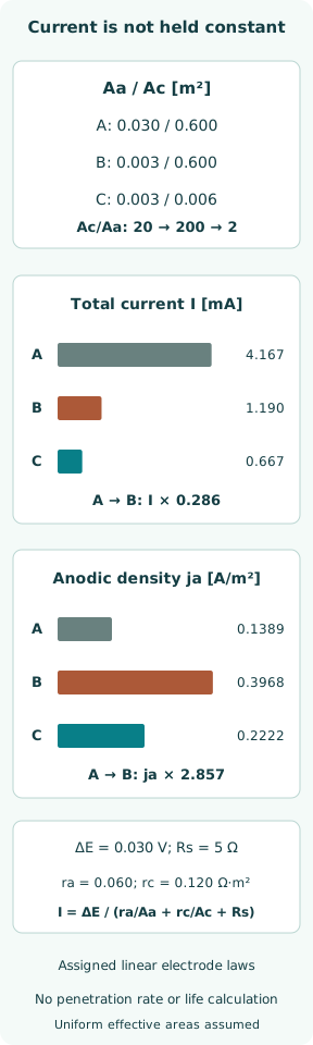
Assign an open-circuit difference ΔE = 0.030 V, area-specific linear electrode resistances ra = 0.060 Ω·m² and rc = 0.120 Ω·m², and a fixed electrolyte resistance Rs = 5 Ω. Define Ra = ra/Aa, Rc = rc/Ac and I = ΔE/(Ra + Rc + Rs). Mean coupling-current densities are ja = I/Aa and jc = I/Ac.
This is an invented lumped circuit with linear polarization laws, not measured properties of a metal pair. It assumes uniform effective areas and holds the electrolyte resistance fixed even as areas change. There is no oxygen-transport ceiling, nonlinear electrode law or evolving passive film. Its purpose is to demonstrate a possible area/current interaction, not to fit seawater corrosion data.
Compare a large and small exposed anode
For case A, choose Aa = 0.030 m² and Ac = 0.600 m², so Ac/Aa = 20. Ra = 2 Ω and Rc = 0.2 Ω; total resistance is 7.2 Ω. The current is 4.167 mA and mean anodic coupling-current density 0.1389 A/m². These quantities follow directly from the assigned circuit and are not corrosion-test measurements.
Case B reduces Aa to 0.003 m² while retaining Ac = 0.600 m². The area ratio becomes 200, Ra rises to 20 Ω and total resistance to 25.2 Ω. Current falls to 1.190 mA, but ja rises to 0.3968 A/m². Shrinking the anode tenfold increases ja by 2.857 times here, not tenfold, because total current is no longer fixed.
Change the cathode and recompute the operating point
Case C keeps Aa = 0.003 m² but assigns an effective cathode area of 0.006 m². The ratio is now 2; Rc becomes 20 Ω and total resistance 45 Ω. Current is 0.6667 mA and ja = 0.2222 A/m². Relative to B, current and anodic density are each multiplied by 0.56, while the anode area stays constant.
The original figure displays total current and mean anodic density in separate panels with their own units. Case C still carries current; a smaller ratio does not mean zero attack or accepted service. The three cases contain no dissolution efficiency, local penetration distribution or time history. Converting their current directly into a failure date would require additional physical evidence not present in this model.
Make coating and insulation decisions at system level
Coating only the anodic member can leave small defects facing a large exposed cathode. That geometry can concentrate the coupling effect at damaged spots. TWI discusses coating and electrical separation among mitigation options. An intact coating and a specified insulating assembly need installation and service evidence; their presence on a drawing is not a permanent guarantee.
Coating both members or reducing effective cathodic exposure can alter the cell, but coating damage, edge coverage and water retention remain relevant. Electrical insulation must include possible bolt, sleeve, support and bypass paths. Required protective bonding and other electrical-safety functions must be resolved in the approved design; casually disconnecting a bonding conductor to suppress corrosion can create a different hazard.
Measure continuity without confusing it with corrosion rate
An electrical continuity check addresses whether a conductive path exists under the test conditions. It does not by itself establish the in-service galvanic current or locate the highest penetration rate. Conversely, a potential reading needs its reference electrode, placement and electrolyte condition to be interpretable. The numerical resistance of an installed network can include parallel routes outside the immediate joint.
NPL recommends verifying intended insulation in the completed equipment and considering connections introduced by later modifications. That makes drawings and change records part of corrosion control. A test should be designed around the intended isolation boundary and relevant safe state, rather than assume a single convenient meter reading describes every path present during operation.
Distinguish coupling current from all metal loss
The net current passing between the two members is the galvanic coupling current. Local anodic and cathodic reactions can also occur on each member, so the coupling current need not equal its entire dissolution current. Corrosion products, deposits, flow and crevices further influence where attack concentrates. An average current density does not map the deepest pit or the remaining load-bearing section.
This is why the circuit example stops before a penetration-rate calculation. A real estimate would require relevant electrochemical data, material dissolution behaviour, wet exposure and spatial distribution, with uncertainty. The absence of a universal current is not a reason to ignore area ratio; it is a reason to combine geometry with the environment and reaction evidence that determines its effect.
Close the joint review with an explicit circuit and scope
A useful joint record identifies both materials and surface states, the ratio convention, exposed-area estimate, likely wetting, all continuity paths and the selected protective measures. It also records how installation and later changes preserve those measures. Where failure is observed, the location and pattern of attack should be compared with that circuit rather than assigned automatically to an alloy mismatch.
The three fictional cases demonstrate a specific result: reducing anode area can lower total current while raising its mean current density. They provide no universally safe ratio, life prediction or cathodic-protection setting. The primary references explain mechanisms and design considerations; neither this NPL guidance nor the short TWI FAQ is adopted as a vessel's classification acceptance rule.
Sources
- TWI — What is galvanic corrosion and how can it be prevented?. Public FAQ accessed 8 October 2026 — Electrical contact, electrolyte, area effects and coating/insulation measures
- NPL — Bimetallic Corrosion, Good Practice in Corrosion Control No.5. Updated guide with 2021 copyright, 34-page official NPL PDF; accessed 8 October 2026 — Sections 2, 3.1–3.6 and 6: circuit conditions, polarization/environment, effective area and limits of the catchment-area principle