Knowledge / Shipyards and ship structures
Lamellar tearing: through-thickness ductility and welded-joint geometry
Connect plate direction, through-thickness ductility and joint restraint using original area-reduction and force-projection examples without predicting tearing.
On this page
A flat finished plate can hide an internal tear below a welded attachment. Lamellar tearing concerns how a rolled plate accommodates strain through its thickness, so a dimensional survey alone does not answer the damage question. The useful distinction is between the material direction being loaded, the ductility available in that direction, and the restraint imposed by the joint.
Locate the weakness in the plate, not just in the weld
Rolling gives a plate longitudinal, transverse and through-thickness directions. Elongated non-metallic inclusions can make resistance to deformation different in those directions. A tensile property measured along the plate does not automatically describe the short transverse direction. The critical region may lie in parent metal beneath an apparently satisfactory weld rather than in the deposited weld metal itself.
TWI identifies the characteristic stepped tear and its relationship to inclusion planes and through-thickness strain. A drawing should therefore show which plate supplies the surface receiving the attachment. Rotating the page does not change the material axes; transferring an attachment to another face may change the relationship between the load path and those axes.
Distinguish restraint from visible distortion
A connection allowed to bend during cooling can accommodate some movement through overall deformation. A heavily restrained cruciform attachment has fewer such freedoms. Preventing observable motion can increase the demand carried internally, although the actual stress and plastic strain require a physical welding model or evidence. A low distortion reading therefore cannot be used as a proxy for low tearing risk.
This is a different question from whether a panel fits the next block. The same fixture can help dimensional repeatability while changing the cracking problem. Record restraint condition, attachment sequence and surrounding stiffness when comparing details. Without those boundary conditions, two nominally identical welds are not necessarily mechanically equivalent during fabrication or after fixture release.
Read Z-quality as a directional property specification
Through-thickness tensile testing measures reduction of area after fracture. The quantity is Z = 100(A0 − Af)/A0, where A0 is the original specimen section and Af the final fracture section, measured under the prescribed test method. It is a percentage of area reduction, not percent thickness compression of the ship plate and not a probability that a weld will survive.
IACS W14 Revision 3 specifies Z25 and Z35 with separate average and individual requirements. Its implementation note refers to construction contracts and plate-certification applications from 1 January 2023. That dated scope must be matched to the project. A material designation, sample location, test validity and certificate identity remain necessary alongside a numerical value.
Calculate the first fictional specimen set
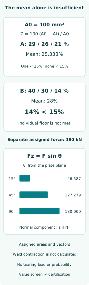
Assign three valid-looking teaching specimens the same initial area A0 = 100 mm² and final areas 71,74 and 79 mm². The reductions are 29%,26% and 21%; their arithmetic mean is 25.333%. One result is below 25%, and none is below 15%. These numbers satisfy the initial Z25 reduction-of-area value screen in the cited W14 edition, including the restriction on the number below the average requirement.
This is deliberately only a value-screen demonstration. No actual sampling, manufacturing approval, fracture location, ultrasonic examination or certification evidence has been supplied. The calculation cannot issue a Z25 certificate or select a grade for an attachment. Keeping the three individual results visible prevents a mean value from concealing the part of the requirement it cannot establish alone.
Use a counterexample to expose the mean-value trap
A second invented set has the same A0 and final areas 60,70 and 86 mm². It produces 40%,30% and 14%, with a mean of 28%. The mean is higher than for the first set, but one specimen is below the Z25 individual floor of 15%. Under the cited W14 initial evaluation, that result is a rejection cause; a favourable mean does not erase it.
The comparison does not simulate production scatter or authorize replacement of an inconvenient result. Invalid tests and permitted retests have their own provisions. A test record needs the original values, fracture location and disposition trail. Substituting a second mean without explaining why another specimen was tested would lose the evidence needed to interpret the result.
Project a force without inventing a welding stress model
Consider a separate static example with an assigned resultant force F = 180 kN, acting at angle θ measured from the plate plane. Its normal component is Fz = F sin θ; its in-plane component is Fp = F cos θ. At 15°,45° and 90°, Fz is 46.587,127.279 and 180.000 kN, while Fp is 173.867,127.279 and zero kN.
Only direction changes in this illustration; the total force remains 180 kN. There is no weld contraction model, local stress concentration, effective loaded area or material failure criterion. The normal component is not a computed tearing load. It helps read a load-path sketch, but cannot rank actual joints whose restraint, force magnitude, inclusions and plastic deformation also change.
Change joint geometry with the whole connection in view
A design review can ask whether shrinkage demand must pass through a susceptible plate, whether the arrangement concentrates it beneath a large attachment, and whether an alternative load path reduces that demand. Those are mechanism-based questions rather than a universal preference for the smallest weld. Weld throat, penetration and attachment strength still have to satisfy the structural purpose.
The material and geometric responses should be considered together. Specifying directional ductility does not remove every restraint effect, and changing the joint does not repair an unidentified material substitution. A proposal to introduce buttering or a different weld arrangement needs its own approved design and procedure basis, including the strength of the complete connection and the inspectability of the resulting geometry.
Inspect the region and orientation that matter
A surface method can reveal a tear only where it is accessible and surface-breaking. An internal planar feature below an attachment raises a different coverage problem. TWI notes the difficulty of radiographic detection in the usual tear orientation and the possible ambiguity between ultrasonic responses from tears and inclusion bands. Method capability therefore depends on geometry and a representative examination procedure.
A clean image is meaningful only for its inspected volume and sensitivity. The inspection record should locate the parent-plate region beneath and adjacent to the weld, identify access limitations and preserve reportable indications. Material certification before welding and examination of the fabricated joint answer related but different questions; neither automatically replaces the other when the fabrication history creates a new damage concern.
Keep material traceability and acceptance references connected
The drawing, purchase requirement and received plate certificate should agree on grade, thickness, directional property designation and identity. After cutting, the identity must still reach the actual attachment location. A certificate for a neighbouring remnant cannot establish the properties of an unmarked piece even if thickness and dimensions match. This is where material genealogy supports the mechanical argument.
The TWI article contains a historical ISO 5817:2007 acceptance reference. That citation is not adopted here as the current contract standard. Establish the governing class rules, agreed quality level and approved inspection and repair arrangements for the actual work. The public W14 text provides a precise cited material framework; it does not replace the project's complete welded-joint acceptance basis.
Report susceptibility, demand and observed condition separately
A useful assessment states the plate axes and identity, evidence for through-thickness ductility, connection geometry and restraint, and what inspection has established. It should distinguish a susceptible material from a demonstrated tear and a proposed mitigation from a qualified fabrication procedure. Otherwise, a favourable certificate or an attractive drawing can quietly become a claim about an unexamined production joint.
The two original calculations make that separation concrete. Area reduction characterizes assigned specimen results and exposes a mean-value error. Force projection describes an assigned vector direction. Neither returns a crack size, time to tearing or safe weld setting. The practical output is a clearer set of material, design and inspection questions, each attached to the evidence capable of answering it.
Sources
- TWI — Defects: lamellar tearing. Public technical article, originally May/June 2000 and subsequently updated; accessed 8 October 2026 — Identification, causes, joint design and detection. Its ISO 5817:2007 reference is historical, not adopted as the project's current acceptance basis.
- IACS UR W14 — Steel plates and wide flats with specified minimum through thickness properties. Revision 3, September 2021; implementation note specifies construction contracts and plate-certification applications from 1 January 2023 — Sections W14.1, W14.3.4, W14.4, W14.5–7; Table 2 distinguishes average and individual reduction of area