Knowledge / Shipyards and ship structures
Resin-chocked machinery foundations: contact, curing and load transfer
Separate resin cure, effective bearing contact and load qualification with original pressure and independent-prism examples for machinery foundations.
On this page
A resin chock is part of a load path, not merely material filling the gap under a machine. Its usefulness depends on the cured material, the surfaces actually in contact and the load transferred through them. A tidy outer edge or an elapsed curing interval cannot establish all three.
Follow force through the installed foundation
The machine foot transfers compression through the chock into the foundation. Hold-down arrangements, structural flexibility and operating forces influence that transfer. The visible outline of the pour is not automatically the bearing area. A void beneath a foot can leave the outer shape intact while changing where force enters the resin and underlying structure.
ITW's November 2020 marine brochure describes poured resin supports for propulsion and other machinery. It provides application context, not a current certificate for a particular installation. The engineering question is whether the selected material and completed geometry carry the defined loads under the required operating conditions, with evidence that reaches the actual support interface.
Keep product data and project qualification separate
A product data sheet reports properties obtained under specified tests or conditions. Compressive strength of a specimen is not interchangeable with an allowable sustained chock pressure beneath a warm engine foot. Temperature, duration, geometry, material condition and the installation approval can change what comparison is appropriate. A numerical margin against one material property may answer the wrong design question.
ITW Technical Guide 643, Version F of April 2025, explicitly directs marine work requiring class review or approval to Guide 692. Its industrial sizing advice is therefore not silently adopted here for class-reviewed ship installations. The relevant current marine instructions, certificate restrictions and machinery requirements must be identified together; the public documents do not supply a completed project qualification.
Construct one transparent compression bookkeeping case
Assign a machine deadweight of 360 kN and four bolt clamping forces of 80 kN each. For this simplified vertical case, clamping contributes 320 kN and the total compression passed through the chocks is 680 kN. Four nominal bearing footprints of 15000 mm² give 60000 mm² in total. The nominal mean is 680000/60000 = 11.333 MPa, using 1 MPa = 1 N/mm².
These forces are assumptions, not values obtained from torque or bolt elongation. The example excludes dynamic forces, thrust and uplift, and it does not solve stiffness-dependent interaction between bolts and support. Adding deadweight and clamping is a declared bookkeeping boundary for this case. It must not become a rule that every real installation has this same load combination or distribution.
Test the mean against unequal force and lost contact
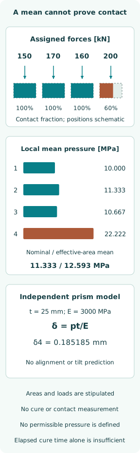
Now assign individual compression resultants of 150,170,160 and 200 kN. They sum to 680 kN, but are stipulated rather than solved from a machine model. Let the first three contact areas remain 15000 mm² and reduce the fourth to 9000 mm². Its contact fraction is 60%, with 40% area loss. The total effective area becomes 54000 mm².
Local mean pressures are then 10.000,11.333,10.667 and 22.222 MPa. Dividing total load by total effective area gives only 12.593 MPa. The highest local mean is 1.961 times the original nominal average. No allowable pressure has been assigned, so neither value yields a pass or fail. The case shows why a global average cannot establish each support's condition.
Isolate the consequence of one reduced footprint
With the fourth force held at its assigned 200 kN, full 15000 mm² contact would give 13.333 MPa. Reducing that area to 9000 mm² raises its mean to 22.222 MPa, a factor of 1.667. Holding force fixed isolates area sensitivity; a real bedplate may redistribute forces as contact changes, so the calculation does not predict the actual response of a damaged support.
Even 22.222 MPa remains an average over the assumed effective patch. Peaks near an edge, a bolt recess or an internal discontinuity are not resolved. Conversely, an apparent surface mark is not automatically a measured loss of bearing area. The assessment needs evidence for the contact geometry and an appropriate mechanical model before a nominal footprint is replaced by an effective one.
Use elastic shortening without inventing machine alignment
For a separate idealization, treat each loaded contact patch as an independent uniform prism, 25 mm thick, with an assigned fully cured modulus E = 3000 MPa. Under each preceding mean pressure, δ = pt/E gives 0.083333,0.094444,0.088889 and 0.185185 mm. The range is 0.101852 mm. Four full nominal prisms would contain 1.500 L before allowing for holes, dams or overpour.
These are independent material-compression calculations. They do not enforce a rigid or flexible machine foot's displacement compatibility and therefore cannot predict bedplate tilt or shaft alignment. The assumed modulus is not an ITW specification. Creep, thermal response and time-dependent relaxation are absent. Using the four results as actual mounting offsets would add a conclusion the model has not earned.
Treat cure as material development, not a clock alone
Resin and hardener must form the intended material under the controlled application conditions. Ambient air temperature does not necessarily equal the steel contact temperature or the temperature inside a reacting pour. A record saying that a nominal number of hours elapsed is incomplete if the relevant material, mixing and thermal conditions are unknown.
The dated Chockfast Orange bulletin 659H labels its cure times approximate and dependent on contact-surface temperature. It is cited for that limitation, not as a universal schedule. This article supplies no mixing ratio or release time. Current product instructions and the approved installation plan must define how material identity, condition and cure evidence are established for the actual geometry.
Distinguish surface hardness from internal contact
An accessible hardness observation can characterize the tested location under its method, but it does not directly map the entire bearing interface. Likewise, a retained sample may document material mixed at a particular time without reproducing the heat history beneath a large machine foot. Each witness has a spatial and process relationship to the installation that should be made explicit.
Contact and cure are connected but different evidence questions. Well-cured resin cannot carry compression across a persistent gap unless the contact state changes, while a full-looking interface does not prove the polymer reached its qualified material state. The original pressure calculation assumes contact areas already known; it does not provide a method to discover them through an external appearance check.
Control the transition from temporary supports to service
Alignment set on temporary supports can change when load transfers to the permanent chocks and hold-down arrangement. The condition in which a survey was taken must therefore be recorded with the relevant support and loading state. Comparing coordinates from different stages without that information can confuse intended transfer with movement caused by an installation defect.
The acceptance package should connect material batch identity, controlled application records, applicable cure evidence, completed contact assessment and the mechanical loading basis. Later retightening, foundation work or equipment replacement can change that basis. No generic bolt adjustment follows from the average-pressure example; a corrective action needs the actual machinery and foundation arrangement, including the consequences for neighbouring supports.
Keep the three acceptance claims visible
Material qualification asks whether the resin has the required properties in the stated conditions. Contact verification asks where compression can actually pass. Load qualification asks whether the full support arrangement meets its requirements. These claims overlap in the physical installation but require different evidence. None becomes complete merely because the other two have attractive paperwork.
The fictional case turns an 11.333 MPa nominal mean into local means up to 22.222 MPa under an assigned unequal distribution and reduced footprint. Its separate prism calculation gives material shortening only. Neither result proves cure, permissible loading or machine alignment. A useful conclusion names the load path and the unresolved evidence, so the final installation decision rests on the actual qualified arrangement.
Sources
- ITW Performance Polymers — Shipbuilding and Repair Solutions. November 2020 manufacturer brochure; accessed 8 October 2026 — Chockfast Orange machinery applications and product distinction
- ITW — Chockfast Orange Technical Bulletin 659H. Revision March 2019, Version H; official public PDF checked 8 October 2026 — Design considerations, application, physical properties and cure schedule
- ITW — Epoxy Chock Design in Industrial Applications, Technical Guide 643. April 2025, Version F; official document checked 8 October 2026 — Description and routing of class-reviewed marine work to Technical Guide 692