Knowledge / Maintenance and reliability
Rotor balancing: mass eccentricity, phase information and residual unbalance
Calculate unbalance force, distinguish one-plane correction from a couple, and solve a complex trial-weight example while keeping balance quality separate from casing vibration.
On this page
Balancing changes the rotor’s mass distribution so that its remaining unbalance meets a defined requirement. A vibration spectrum can suggest a once-per-revolution problem, but it does not by itself state the correction mass or prove that unbalance is the only cause. Radius, phase, correction planes, speed and the response of the mounted machine all enter the balancing problem.
Unbalance has both magnitude and angle
A point mass m at radius r contributes an unbalance vector U =mr. Its units may be g·mm or kg·m; the vector angle locates the contribution relative to a declared rotor reference. At angular speed ω, the rotating-force amplitude is F =Uω² when U is expressed in kg·m. The square-speed dependence makes a small mass error increasingly important at high speed.
For an independent force example, 10 g at 100 mm gives 1000 g·mm = 0.001 kg·m. At 3000 rpm, ω = 2π ×3000/60 = 314.159 rad/s, so F = 98.696 N. This is an excitation-force amplitude, not a predicted bearing-housing vibration. Structural stiffness, damping and other forces determine the measured response.
A balanced force sum can still leave a couple
Two equal unbalance vectors at opposite angles in different axial planes can cancel their resultant force while creating a rotating couple. For example, 500 g·mm in each of two opposite vectors separated by 200 mm gives couple unbalance 100000 g·mm² = 0.0001 kg·m². At 3000 rpm its moment amplitude is 9.870 N·m, despite the zero vector force sum.
Schenck distinguishes static and couple unbalance and provides separate one- and two-plane methods. A single correction plane cannot generally cancel both resultant unbalance and an independent couple. Two-plane correction provides two independent vectors, but those vectors interact through the rotor and supports; correcting one end in isolation may worsen the other.
Rigid behaviour is an operating-range assumption
ISO 21940-11 covers rotors with rigid behaviour and addresses residual unbalance, correction planes, tolerance allocation and errors. Its public listing includes Amendment 1:2022. Flexible-rotor behaviour is outside that part’s scope. A rotor is not classified solely by whether it looks thick or short; bending response over the relevant speed range matters.
Likewise, a rotor balanced on a machine or mandrel can change its effective unbalance when assembled with other parts or reseated. Runout, dirt at locating faces, component indexing and fixture error need consideration. Balance correction is not a substitute for correcting a loose support, rubbing, misalignment or a resonance that dominates the observed response.
Phase links a trial mass to the machine’s response
A single-plane linear model can be written V =αU, where V is a complex synchronous vibration response and α is a complex influence coefficient for a fixed speed, mounting and sensor arrangement. α contains amplitude sensitivity and phase shift. Sensor phase is therefore not automatically the physical heavy-spot angle.
For the numerical demonstration, use one consistent amplitude convention, angular reference and positive direction. A known trial vector Ut produces ΔV =V1 −V0, so α =ΔV/Ut. A changed speed, sensor position or mounting condition can invalidate the coefficient. The example assumes repeatable linear response and an identifiable unbalance contribution; it is not a live trial-weight instruction.
Worked example: determine the correction vector
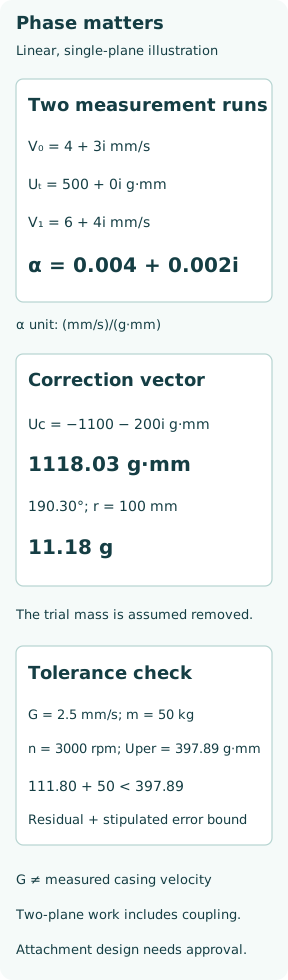
In a separate hypothetical trial, let the baseline response be V0 = 4 +3i mm/s, with magnitude 5.000 mm/s and phase 36.870°. Add trial unbalance Ut = 500 +0i g·mm, and suppose the response becomes V1 = 6 +4i mm/s. The complex change is 2 +1i, not the difference between the two scalar amplitudes.
Then α =(2 +1i)/500 = 0.004 +0.002i (mm/s)/(g·mm). Relative to the original baseline, the correction is Uc =−V0/α =−1100 −200i g·mm. Its magnitude is 1118.034 g·mm and angle 190.305° in the stipulated rotor-angle convention. At 100 mm correction radius, equivalent added mass is 11.180 g. The calculation assumes the trial mass is not retained in that baseline correction.
Verify the new state rather than trusting the predicted zero
The linear prediction gives V0 +αUc = 0, but actual residual response must be measured. Suppose the verification response in the same model is 0.4 +0.3i mm/s. Its equivalent residual vector is Vres/α = 110 +20i g·mm, with magnitude 111.803 g·mm. This inference depends on the same coefficient and absence of a significant unrelated synchronous contribution.
Trial and permanent corrections must have approved attachment integrity and clearance for the operating speed. The permissible trial size and test speed come from the equipment procedure, not the arbitrary numbers above. A successful mathematical cancellation does not establish the strength of an attachment or authorize material removal from an unapproved rotor location.
A balance grade is not a casing-velocity limit
For an illustrative rigid-rotor tolerance calculation, stipulate grade G = 2.5 mm/s, rotor mass 50 kg and maximum service speed 3000 rpm. This is a chosen example target, not a recommendation for a rotor type. The permissible specific unbalance is eper =G/ω = 0.0079577 mm = 7.9577 µm. Multiplying by 50000 g gives Uper = 397.887 g·mm.
BTI explains this conversion from grade, rotor mass and service speed. Although G has velocity units, it is the product of permissible mass eccentricity and angular speed. It is not the measured casing vibration velocity. Comparing a 5 mm/s sensor reading directly with G2.5 would mix different physical quantities.
Acceptance needs uncertainty and correct plane allocation
If the single-plane example’s 111.803 g·mm residual has a separately stipulated conservative uncertainty bound of 50 g·mm, its upper bound is 161.803 g·mm, below the assumed 397.887 g·mm target. This demonstrates a declared acceptance calculation, not a certificate for a real rotor. The uncertainty bound would need evidence from the actual measurement process.
For a two-plane rotor, the total tolerance is allocated using the relevant geometry and specification; it is not always divided equally. The two measured responses form a vector, and trial corrections establish an influence matrix containing cross-plane effects. A poorly conditioned matrix or inadequate trial influence can magnify errors. Appropriate repeatability checks and final measurements in all relevant planes are needed.
A useful balance record preserves the complete basis
Record rotor identity and assembled state, mass, service and balancing speeds, rigid/flexible basis, correction/tolerance planes, reference angle and rotation direction, sensor positions, amplitude convention, trial vectors, final corrections, residual results and uncertainty. Note whether a trial mass was removed or retained and whether correction was by adding or removing material.
The result should demonstrate a residual-unbalance requirement and separately the installed machine’s vibration acceptability where required. The important chain is mass distribution → rotating excitation → measured amplitude and phase → verified correction. A lower overall vibration number alone does not show that all the required balancing conditions have been met.