Knowledge / Maintenance and reliability
Safety-valve tests: set pressure, blowdown and bench-test boundaries
Distinguish opening, reseating and capacity evidence, calculate blowdown on the right pressure basis, and explain why service backpressure and temperature can change a cold bench setting.
On this page
A safety valve that opens at a recorded bench pressure has passed a particular observation under particular conditions. That result is valuable, but it does not alone establish the installed relieving capacity, the reseating behaviour on another fluid or the effect of the discharge system. A useful test record states exactly which function was demonstrated and connects the test conditions to the valve’s approved service basis.
Define the event before assigning it a pressure
Set pressure is tied to the opening criterion prescribed for the valve and test method. First leakage, an audible event, a specified lift and a rapid pop are not automatically equivalent observations. The applicable procedure must define the event. A seat-leakage check below the set point answers a different question from an opening-pressure test.
Spirax Sarco explains how a rapid-opening valve’s flow forces and exposed area change after initial lift. The closing path therefore need not retrace the opening path. Record the valve type, test fluid, pressure basis and opening/reseating criterion before comparing numbers from different reports.
Blowdown is the opening-to-reseating difference
For the stipulated convention used here, blowdown is the difference between the observed set pressure Ps and reseating pressure Pr, expressed either as pressure or as 100(Ps − Pr)/Ps percent. Use gauge pressures consistently for this example and state that basis. The word does not refer here to a boiler’s solids-removal blowdown system.
In an original numerical example, Ps = 10.00 bar g and Pr = 9.30 bar g give 0.70 bar blowdown and 7.00% of set pressure. That calculation says nothing yet about acceptability: the permitted behaviour comes from the applicable valve specification and service requirement. It is not a recommendation to adjust a valve to 7%.
Overpressure and accumulation use different references
Suppose the same illustrative system has a relieving pressure of 10.80 bar g and a stipulated maximum allowable working pressure, MAWP, of 10.50 bar g. Overpressure above the 10.00 bar g set point is 0.80 bar, or 8.00% of set pressure. Accumulation above MAWP is 0.30 bar, or 2.857% of MAWP.
The two percentages differ because both their subtracted reference and their denominator differ. When set pressure equals MAWP they may coincide numerically, which can hide the distinction. The example does not establish a permitted accumulation, sizing pressure or code limit; it only makes the reference values explicit. Capacity calculations also need the proper absolute pressures and fluid properties for the selected flow model.
A bounded-error example shows why the reported basis matters
Assume independently bounded measurement errors of ±0.02 bar for each of the two observations, without claiming this is a required instrument accuracy. The smallest possible blowdown percentage in those bounds is (9.98 − 9.32)/9.98 × 100 = 6.613%. The largest is (10.02 − 9.28)/10.02 × 100 = 7.385%.
This is a conservative interval calculation, not a statistical confidence interval. A shared gauge offset can correlate errors and partly cancel in the pressure difference; drift, repeatability and event detection can add other contributions. The uncertainty model must match the actual measurement chain. Rounding the displayed readings more finely does not reduce those contributions.
Service conditions can require a different cold setting
LESER’s manufacturer procedure identifies cold differential test pressure, CDTP, when temperature or constant superimposed backpressure requires a correction. Its test-medium table also distinguishes service and approval cases. The actual valve’s current approved procedure governs; an older generic handbook table should not be used as a substitute for that instruction.
CDTP is not obtained by one universal correction applicable to every valve. Spring temperature response, bonnet pressure reference, bellows or piston balancing, pilot arrangement and the backpressure regime can matter. A water test, an air test and a steam test need not reproduce the same opening dynamics or reseating behaviour even when a pressure gauge reads the same value.
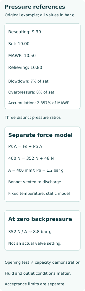
Worked force balance: why the bonnet reference changes the answer
Use a separate ideal conventional valve whose spring bonnet is vented to the discharge side, with a net backpressure closing area equal to nozzle area A = 400 mm² = 0.0004 m². Hold temperature fixed and ignore friction and dynamic forces. The static opening balance is PsA = Fs + PbA. This is the specific arrangement described in Spirax Sarco’s Figure 9.2.1(a), not a rule for all safety valves.
For Ps = 10 bar g and constant Pb = 1.2 bar g, the inlet force is 400 N and net backpressure closing force 48 N. The ideal spring force is therefore 352 N. With that same spring force and zero backpressure, the model’s bench opening pressure is 8.8 bar g. Conversely, a spring set to 400 N at zero backpressure would open at 11.2 bar g in this model’s service condition. These values illustrate the force balance; they are not actual CDTP adjustment instructions.
Superimposed and built-up backpressure answer different questions
Superimposed backpressure exists before the valve opens. Built-up backpressure is generated by discharge flow. The latter is linked to the outlet system and changes while the valve relieves. A bench open to atmosphere does not reproduce that installed outlet boundary. Balanced designs reduce specified backpressure effects, but their permissible operating range and vent arrangements still need verification.
An arbitrary outlet-pressure subtraction is particularly unsafe when the valve design differs from the ideal force model above. Use the actual manufacturer’s correction and capacity data, including the allowed variable-backpressure conditions. The same outlet system can influence both flow capacity and stability; an opening-point observation alone does not establish either one.
A setting stand may not have the flow needed to demonstrate capacity
Spirax Sarco distinguishes a set-pressure stand from a capacity demonstration. A small supply can reach the opening event but lose pressure as soon as appreciable flow begins. It cannot then reproduce sustained full lift, the required discharge or a representative closing transient. This limitation belongs in the recorded test scope.
Installed protection additionally depends on the certified valve capacity for the fluid and relieving conditions, the credible required relief load, inlet losses, outlet backpressure and the installed configuration. A passing set-pressure result and a passing seat-tightness result are separate evidence items. Neither should be relabelled as a complete installed overpressure-protection demonstration.
Preserve the as-found result and the final test scope
A meaningful record identifies the valve and protected equipment, as-found observations, applicable procedure, medium and temperature, gauge references and calibration, pressure ramp/event method, repeated readings, reseating evidence, leakage checks and final sealed state. If reseating or flow capacity was not demonstrated by the setup, state that specific boundary in the test record.
Adjustments and disassembly require the qualified procedure and responsible personnel; the calculations above are for interpreting evidence. After the valve is returned to service, correct orientation, discharge connection, unobstructed required vents and approved isolation status remain part of the installed configuration. The conclusion should say what the evidence proves, with set pressure, blowdown and capacity kept as distinct functions.