Knowledge / Navigation and marine safety
Lifeboat release hooks: locked state, load path and maintenance evidence
Distinguish hook engagement, local load geometry and maintenance evidence with an original signed-moment example that establishes no release or adjustment setting.
On this page
A lifeboat can appear ready while an important part of its suspension remains poorly evidenced. The handle position, the engagement of a retaining component and the path taken by the suspended load are related, but they are different physical facts. Understanding that distinction helps explain why release-hook maintenance is a specific technical activity rather than a by-product of completing a drill.
Follow the suspension into the boat
The suspension force passes through connected pieces: the fall termination, the hook assembly, its attachment and the boat structure. A local retaining component may control whether that path remains closed. An examination therefore needs the actual assembly drawing and equipment identity, including modifications; the external resemblance of two hooks is not evidence that their internal load paths are identical.
This article concerns what must be demonstrated about that path. It does not describe how to release, reset, bypass or adjust a mechanism. A free-fall boat and a davit-launched boat have different arrangements, and an illustration of one cannot be transferred to the other merely because both have equipment called release gear.
Name the state that an indication represents
A handle can reach its indicated position while another part of the mechanism does not achieve the intended engagement. Conversely, a visible marking may be difficult to interpret even when the mechanism is correctly engaged. The diagnostic question is what the indication is physically connected to and which part of the completed state it can actually establish.
The distinction is especially important when a cable, linkage or several hooks connect one control to more than one load-bearing assembly. A common command does not demonstrate equal achieved engagement at every end. Evidence should identify each relevant assembly, the manufacturer's defined indication and the permitted means of verification, without treating an improvised look or pull as a substitute.
Use a local moment model, not a hook design
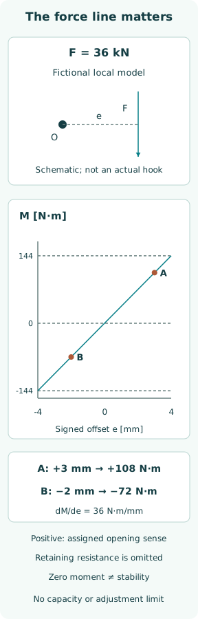
Consider a fictional planar rigid body with a pivot O and one downward force F = 36 kN. Let e be the signed horizontal separation between O and the force's vertical line of action. Define a positive moment as an opening tendency for this invented body. Then M = F e, with e in metres and M in newton metres.
The drawing represents only the force line and reference pivot. It contains no latch profile, contact angle, spring, cable, friction or locking geometry. The pivot is an analytical reference, not a proposed hole or adjustment point. A real hook may transfer force through several contacts, so this model cannot identify its opening tendency from an external photograph.
Keep the sign and unit conversion visible
For configuration A, assign e = +3 mm = +0.003 m. The moment is +108 N·m. For configuration B, assign e = −2 mm = −0.002 m; the moment is −72 N·m. Both configurations carry the same imposed 36 kN force, yet the moments act in opposite directions under the declared sign convention.
One millimetre of signed offset changes this model's moment by 36 N·m. The difference between A and B is 180 N·m because their force lines are 5 mm apart. These are invented geometric comparisons, not manufacturing tolerances or permissible wear. Their purpose is to make the sensitivity to where force acts distinct from the size of that force.
Read the graph without assigning a locking capacity
The original figure plots M against e from −4 to +4 mm, with a slope of 36 N·m per millimetre. It highlights the two assigned configurations. The zero crossing describes a line of force passing through O; it does not show a stable locked state. Stability would require how contact forces and geometry change after a small displacement.
Nor does a negative plotted moment prove safety. A different load direction, a changing contact point or a damaged retaining part could alter the real behaviour. The model omits the resisting moment entirely. There is consequently no margin, factor of safety, release force or allowable adjustment to read from the distance between either point and the zero line.
Separate release function from retained engagement
MSC.402(96), section 6.2.4, addresses release devices, free play, hydrostatic interlocks where fitted, control cables and hook fastening; its note prohibits maintenance or adjustment while hooks are loaded. These are specific equipment concerns, not a generic visual approval. They explain why a service record must identify the actual mechanism and work scope.
The presence of a hydrostatic interlock is evidence of a particular design function, not proof of the complete mechanical state. The interlock, the release command path and the load-retaining contacts answer different questions. Interpreting one as a universal guarantee hides the remaining dependencies. No interlock override or substitute retaining arrangement follows from the signed-moment example.
Make service evidence match the equipment
The useful connection in a maintenance record is between an identified assembly, the applicable instructions, the examination performed and the resulting condition. A certificate for a different make or type cannot establish the competence scope for this one. A completed work order also needs a traceable result; the word serviced alone leaves the relevant observations unknown.
MSC.402 sections 4–5 distinguish routine shipboard work from certified examination and testing and require associated reports and records. In an engineering review, that framework supports asking which activity was completed and by whom. It does not justify extending a routine inspection into disassembly or a loaded trial based on this article.
Treat changes as changes to the evidence chain
A replacement cable, altered attachment, repaired foundation or changed component can affect how a release mechanism reaches and retains its intended state. A parts list records what was fitted, but it does not by itself show correct system-level operation. The review must connect the change to the assembly's approved configuration and the evidence required for restoration.
A useful defect description separates the observation from its interpretation: incomplete visible travel, an unreadable indication or a recorded clearance outside the manufacturer's criterion are different findings. Assigning all of them the label hook failure can obscure the required investigation. Equally, absence of a visible defect cannot establish internal condition or erase an unresolved maintenance finding.
Read the version boundary as part of the claim
MSC.559(108), effective 1 January 2026, replaces MSC.402 paragraph 6.2.3 and adds ventilation-system examination where fitted. It is relevant to the boat-maintenance framework even though it does not provide the fictional hook dimensions used here. The original 2016 resolution alone is therefore an incomplete version reference for that framework.
The official MSC.590(111) public file was still a certification placeholder when checked on 8 October 2026. Its substantive amendment text was unavailable there. This article does not claim to reproduce a fully consolidated current code or infer an effective date from that placeholder; equipment-specific requirements must be established from the applicable controlled documentation.
Conclude only what the mechanics demonstrate
The case demonstrates that force magnitude and signed local moment are separate quantities. The same force gives +108 N·m or −72 N·m when its assigned line of action moves across the chosen pivot. That is a reason to investigate real geometry carefully, not a recommendation to move a component in order to obtain a preferred sign.
A credible locked-state claim combines the manufacturer's defined engagement evidence with the applicable examination, records and actual load path. Drill attendance, handle position and a simple force calculation cannot supply those missing elements. The analytical boundary is deliberate: no strength, release sequence, service interval or authorization to occupy a suspended boat is established by the example.
Sources
- IMO MSC.402(96): maintenance, examination and testing of lifeboat systems. Adopted 19 May 2016; read with MSC.559(108), effective 1 January 2026; not asserted to be an exhaustive consolidation — Annex §§4–5, 6.2.4 and note 2, 6.2.5–6.2.6; actual PDF inspected 2026-10-08
- IMO MSC.559(108): amendment to MSC.402(96). Adopted 23 May 2024; in force 1 January 2026 — Annex replacement §6.2.3 adds ventilation-system examination; actual PDF inspected 2026-10-08
- IMO MSC.590(111): public certification placeholder. Listed in the official 2026–27 resolution index; public file states awaiting certification on 2026-10-08 — One-page file contains no amendment text; no substantive or effective-date claim derived from it