Knowledge / Navigation and marine safety
Liferaft float-free operation: hydrostatic release units and the connection chain
Trace the separate functions behind liferaft float-free operation and use a hydrostatic-pressure comparison to show why an HRU trigger alone cannot establish deployment.
On this page
A hydrostatic release unit responds to submergence, but a usable liferaft depends on more than that response. Restraint release, unobstructed movement, painter function, inflation and final separation belong to a connected physical chain. A component can perform its own task while a different interface prevents the intended outcome.
Define float-free as an outcome chain
The intended outcome is an inflated raft separated from a sinking vessel and available for use. That outcome contains several functions which should not be compressed into the single phrase HRU works. Releasing a restraint is different from allowing the container to move; movement is different from inflation; inflation is different from eventual separation at the designed connection.
MCA MGN 343 explains these linked functions and distinguishes automatic float-free operation from manual launch. Its explanation is used here to identify interfaces, not to supply an installation recipe. The particular raft, release unit, restraint and painter arrangement must be identified together before their compatibility can be assessed.
Understand what hydrostatic pressure supplies
A submerged pressure-responsive element experiences water pressure that increases with vertical depth below the local free surface. For stationary water of constant density, gauge pressure is p = ρgh. Gauge pressure is relative to surface atmospheric pressure. It is not the absolute pressure, the depth of the seabed or the vertical position relative to a fixed point on the ship.
The equation describes the water field. It does not describe the unit's internal response, hysteresis, geometry, drainage or actuation mechanism. A pressure calculated at one depth therefore cannot establish that an unidentified device has operated. A technical assessment must connect the environmental input to the specific unit's approved characteristics rather than substitute hydrostatics for equipment evidence.
Calculate an original equal-depth comparison
Choose a fictional comparison depth h = 2.40 m and gravitational acceleration g = 9.81 m/s². Assign fresh-water density 1,000 kg/m³ and sea-water density 1,025 kg/m³. These are teaching inputs, not measurements of a particular port. The model assumes a stationary, incompressible water column, uniform density and a free surface at atmospheric pressure.
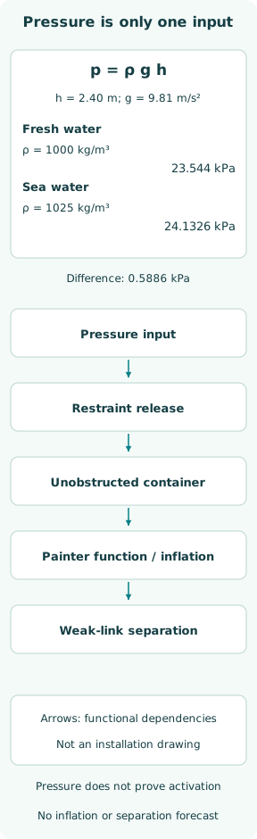
Fresh-water gauge pressure is 1,000 × 9.81 × 2.40 = 23,544 Pa = 23.544 kPa. The sea-water result is 24,132.6 Pa = 24.1326 kPa. A pascal is one newton per square metre, so multiplying density by acceleration and depth produces pressure, not a release force or an amount of stored energy.
Compare pressure changes without inventing a trigger
At the chosen depth, the difference is 0.5886 kPa and the sea-water to fresh-water ratio is 1.025. In the same sea-water model, depths of 1.20 and 3.60 m give 12.0663 and 36.1989 kPa respectively. The linearity follows directly from the assumed constant density; it is not a test result for any release unit.
No activation threshold is assigned to the case. Without a specified pressure-sensitive area, internal load path and validated mechanism response, these numbers cannot yield a knife force, release reliability or actual actuation depth. Even supplying a nominal area would leave mechanism losses and tolerances unresolved. The case is deliberately a pressure comparison rather than a component qualification.
Keep the functional arrows distinct from connections
The figure places pressure above the functional chain: restraint release, container clearance, painter function with inflation, and weak-link separation. The arrows mean dependency. They are not ropes, fittings or a sequence for a person to perform. Their vertical spacing is graphical and conveys neither sinking speed nor elapsed time between events.
The distinction matters because an attractive chain diagram can otherwise be mistaken for rigging guidance. A real arrangement contains detailed connections and approved load paths that this diagram intentionally does not draw. The calculated pressure can inform the first environmental input while leaving every downstream function unresolved; the figure shows those unanswered questions instead of hiding them.
Treat restraint and painter functions separately
The restraint keeps the container in its intended stowed position; the painter participates in deployment and inflation. Treating every visible line as an interchangeable tether loses those different purposes. A line that appears stronger may defeat a required separation function, while a connection that releases too early may prevent the intended inflation function from occurring.
MGN 343 warns that incorrect fitting can defeat either automatic or manual operation and rejects arbitrary cord as a replacement weak link. This article gives no alternative line, knot, attachment point or breaking-load specification. Evaluation must use the approved arrangement and instructions for the actual equipment combination, including the manual-launch function that a float-free-only sketch leaves out.
Examine clearance as a three-dimensional question
After the restraint releases, the container still needs a viable path away from its stowage. A nearby rail, cover, cable, overhanging platform or added equipment can interfere even though the release unit itself is accessible. The relevant geometry is the path of the container in the possible vessel attitudes, not only the space available while the ship is upright.
A photograph from one direction may conceal an obstruction. Drawings and physical inspection answer complementary questions, especially after deck alterations. This is not a recommendation to simulate a sinking or pull a loaded assembly through its supports. It is an engineering reason to preserve the float-free envelope and verify changes against the vessel's approved stowage arrangement.
Read the product variant and its markings
Hammar's H20 product sheet distinguishes depth variants and service-life markings. Its filename says v.2.0 while the printed sheet says 2022 Ver.1; that inconsistency is retained in the source record. The sheet is a manufacturer example, not evidence that all HRUs share one depth range, replacement date or weak-link characteristic.
The useful identity includes the exact variant, marking, installation context and corresponding instructions. An expiry label on one component does not establish the condition of the painter, container or cradle. Conversely, a recent raft service does not silently renew a separately limited component. Evidence should follow each item's role without treating a single date as the life of the entire chain.
Preserve what each observation can establish
A readable identity label can support component identification. An unobstructed-stowage observation can support a geometric claim. A service record can support the work it actually documents. None alone demonstrates the complete automatic sequence under a sinking condition. The record should make those claims distinct so that a missing interface is visible to a reviewer.
The same care applies after replacement. A unit with the correct general name can have the wrong variant or an incompatible associated connection. The pressure equation cannot discover that mismatch. Resolving it requires the installed combination's documentation and competent inspection within the authorized maintenance scope, rather than experimenting with substitutions to see whether the raft can be made to release.
Close the case at the pressure boundary
The numerical conclusion is narrow: at 2.40 m in the stated static columns, gauge pressure is 23.544 kPa or 24.1326 kPa. The 2.5% density change produces a 2.5% pressure change at equal depth. No corresponding percentage change in release depth, deployment time or survival-craft availability has been established.
The larger engineering lesson is that a pressure-responsive component and a completed float-free function are different claims. The evidence must connect the restraint, clear path, painter, inflation and separation functions in the actual approved arrangement. A hydrostatic calculation supplies neither deployment certification nor permission to modify those connections, and it cannot guarantee a raft's availability in a real casualty.
Sources
- MCA MGN 343 (M+F): hydrostatic release units and liferaft float-free arrangements. MGN 343, April 2007; current active-MGN collection still lists it on 2026-10-08 — §§1–2: separate automatic and manual functions, obstruction-free stowage and manufacturer instructions; actual 11-page PDF inspected
- CM Hammar: H20 hydrostatic release units for raft, product data sheet. File name KOM-2454 v.2.0; printed document says 2022 Ver.1; version discrepancy preserved, not silently resolved — Page 1: depth variants, weak link and service-life markings; manufacturer page and actual two-page PDF inspected 2026-10-08; not a universal installation instruction