Knowledge / Navigation and marine safety
Radar ghost echoes: multiple reflection, indirect echoes and target verification
Trace original reciprocal radar paths to distinguish range multiples, indirect bearing shifts and the evidence needed to classify an echo.
On this page
An unexpected radar echo may be produced by a real target along a path that places its return at a misleading displayed position. Explaining that possibility requires tracing the signal, not simply labeling the mark a ghost. Range, bearing and target identity are separate parts of the argument.
Define the family of ghost echoes
“Ghost echo” is a broad descriptive label rather than one physical mechanism. Extra reflections can lengthen a signal path, an indirect path can change the direction from which energy reaches the antenna, and antenna side lobes can associate a return with an unintended bearing. Similar-looking marks need not have the same cause.
The NGA-hosted Radar Navigation and Maneuvering Board Manual, Seventh Edition (2001), distinguishes indirect echoes, multiple echoes, side-lobe effects and second-trace echoes on pages 152–155. It is used here for those stable physical distinctions. The article does not infer the processing features of a present-day radar from that historical edition or present its illustrations as a modern product interface.
Connect range and bearing to different measurements
In the ideal pulse-ranging calculation, displayed range is half the assumed propagation speed multiplied by round-trip delay: R_ind = c₀τ/2. A longer total path can therefore yield an indicated range beyond the actual straight-line distance. The factor of two belongs to the ordinary outward-and-return interpretation, even when the actual path contains additional segments.
Bearing depends on the antenna direction associated with the return. An indirect reciprocal path can make that direction point toward a nearby reflector instead of the genuine target. The numerical case below uses true bearings in a north-up plane, so changing bearing reference cannot explain the discrepancy. It assumes ideal ranging and ignores bandwidth, angular beamwidth and processing errors to isolate path geometry.
Trace repeated reflections
For a target at range R, the direct out-and-back path is 2R. If an ideal return repeats a target/own-ship reflection sequence, its total path can become 2nR. Applying the usual range conversion yields nR. With R = 600 m, the ideal second and third ranges are consequently 1,200 and 1,800 m.
These distances describe path lengths, not echo strength. A repeated route needs suitable reflecting surfaces and sufficient received energy to produce an observable mark. The geometry alone provides neither. Even a clean series of marks at approximately repeated ranges is therefore evidence for a hypothesis, not proof that all but one contact can be discarded or that no real object occupies a similar range.
Trace an indirect reciprocal path
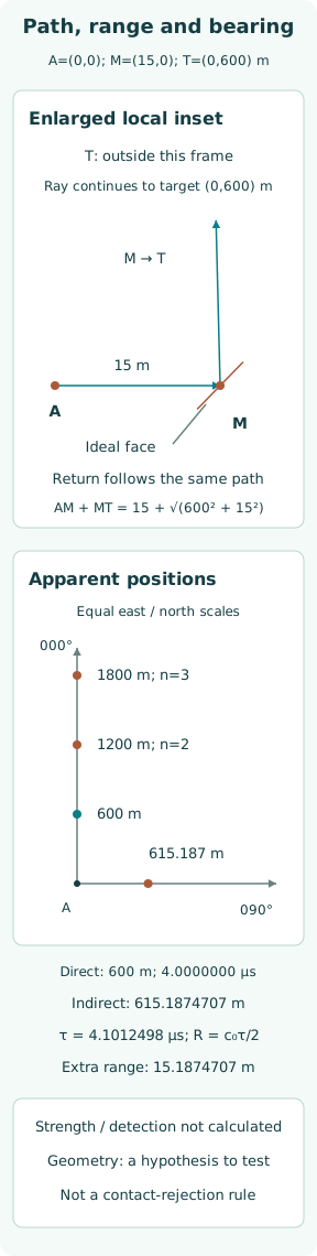
Set antenna A = (0, 0), real target T = (0, 600 m) and an ideal nearby reflector M = (15 m east, 0). Assume a reflecting face oriented to permit A→M→T and the reciprocal return T→M→A. A face normal along the bisector of the appropriate incident and reflected directions provides a physically consistent specular construction.
The final segment reaches A from the east, so the path is associated with 090° true even though T is due north at 000°. The enlarged near-antenna inset shows only the local turn at M; the distant target lies outside it. Drawing a ray through a convenient corner without a compatible reflecting orientation would not be a valid physical explanation, however attractive the resulting triangle.
Work the original geometric comparison
The direct round trip is 1,200 m. With c₀ = 3.00 × 10⁸ m/s, delay is 4.0000000 µs and indicated range is 600 m. The one-way indirect distance is AM + MT = 15 + √(600² + 15²) = 615.1874707 m. Its reciprocal round trip yields 4.1012498 µs and the same 615.1874707 m indicated range.
The extra indicated distance is 15.1874707 m. Thus an indirect return need not have exactly the direct target’s range. The manual’s approximate same-range description depends on the additional local path being negligible. Here, the invented 15 m displacement makes that approximation visibly imperfect. The original plot preserves a common spatial scale for the apparent positions while the separate enlarged inset reveals the nearby reflection.
Keep side lobes and second-trace echoes separate
Side-lobe reception concerns the antenna’s directional response: strong returns can be associated with directions away from the main beam. A previous-pulse or second-trace echo instead concerns timing ambiguity, when energy from an earlier transmission is interpreted in a later timing cycle. These mechanisms are different from repeated reflections of one pulse along a longer path.
Consequently, the 1,200 and 1,800 m marks in this invented case are specifically ideal multiple-reflection hypotheses. No pulse-repetition interval was supplied, so the case calculates no second-trace ambiguity range. No antenna pattern was supplied, so it predicts no side-lobe arc or angular extent. Preserving those missing inputs prevents several mechanisms from being merged under one untestable explanation.
Use observations to test competing explanations
A useful hypothesis predicts more than a single mark. An onboard indirect path relates apparent bearing to installation geometry; repeated reflections relate candidate ranges to a genuine reflector; a timing ambiguity relates a return to transmission timing. Observations over changing geometry can strengthen or weaken those specific predictions, provided the observations themselves retain trustworthy time and reference information.
A single convenient match is weak evidence when several explanations remain possible. An actual object can coincide with a proposed ghost location, and more than one mechanism may operate together. The teaching calculations deliberately contain no measured amplitudes, tracks or clutter. They show what to calculate if a path is assumed, not how to assign certainty to an unexamined display.
Preserve independent target evidence
Visual information, appropriate charted features and another genuinely independent radar observation can address different parts of a disputed contact. Their usefulness depends on conditions and coverage. Two screens driven by the same antenna and processing stream may repeat the same artifact. Agreement between them cannot automatically be counted as two independent detections of an external object.
The absence of an AIS report does not establish that an echo is false. Nor does finding a plausible AIS symbol prove that every nearby radar mark belongs to it. This article supplies no association or rejection rule. The relevant task is to preserve unresolved contact evidence while testing the path explanation, with actual equipment guidance and navigational responsibilities applying to the real situation.
Record installation and processing context
An interpretable investigation records antenna location, nearby structures, the relevant orientation, range scale, acquisition time and available processing settings or status. If a suspected reflector is part of the installation, its physical geometry matters. A sketch that relocates it for convenience can change the predicted bearing and path length, invalidating the very explanation being tested.
Processing can affect what becomes visible, but this case provides no manufacturer algorithm, suppression threshold or gain-setting prescription. Its figures are original geometric diagrams rather than captured radar screens. A real review would need the applicable manual and installation information, along with observations that distinguish a persistent physical path from transient clutter or a display/processing effect. Those sources must match the actual equipment version.
State the limits of ghost classification
The completed calculation produces four distinct ideal plotted positions: the direct target at 600 m north, two range multiples at 1,200 and 1,800 m north, and an indirect hypothesis at 615.1874707 m east. The last position comes from both extra path length and redirected bearing. One real target can therefore support several path explanations without every plotted position representing a separate physical target.
What remains unproved is whether any of those indirect or repeated paths produces a detectable return in a real installation, and whether an observed contact actually follows it. Reflector size, polarization, obstruction, antenna pattern, sea state and receiver processing were omitted. The correct endpoint is a bounded geometric hypothesis with testable consequences, not permission to suppress an unexplained contact or treat its area as clear.
Sources
- NIMA/NGA Publication 1310, Radar Navigation and Maneuvering Board Manual, Chapter 4. Seventh Edition, 2001, verified on official title page — Printed pp.152–155: Indirect (False) Echoes, Multiple Echoes, Side-lobe Effects, Second-Trace (Multiple-Trace) Echoes; Figs.4.4–4.10