Knowledge / Navigation and marine safety
Rudder force and stall: effective inflow within the propeller slipstream
Calculate three original effective-inflow cases and distinguish commanded rudder angle, normal force and the separate evidence needed for stall.
On this page
A rudder-angle indication reports where the blade has moved. It does not directly report the angle of attack seen by the water or the resulting steering force. The propeller slipstream and local lateral flow can change both, even while the indicated rudder angle stays fixed.
Follow force beyond the steering actuator
A steering actuator supplies motion and torque to the rudder stock. Hydrodynamic loading arises from the surrounding flow acting on the blade. These are connected stages, but a pressure or position measurement in the steering gear does not directly measure the external flow field. A fully reached angle can coexist with a different force than expected.
Wärtsilä’s rudder description identifies the hydrofoil action and the benefit of placement in the propeller stream. This article follows that external-force mechanism. It does not diagnose leakage, valve response or hydraulic redundancy. Distinguishing the mechanism matters because changing an actuator explanation cannot repair a force estimate that used the wrong local velocity or incidence.
Draw the local inflow
The water reaching a rudder has already interacted with the hull and, where applicable, the propeller. Axial speed need not equal the ship’s speed through water, and the slipstream may cover only part of the blade. Lateral inflow also reflects the selected motion state and interaction model. One uniform speed is therefore a modeling choice rather than a direct consequence of the speed log.
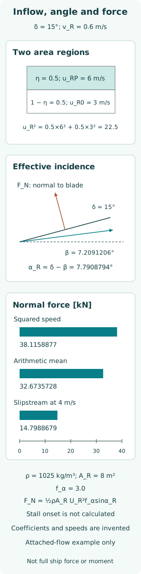
In the original example, divide the rudder into equal covered and uncovered areas. Prescribe axial speeds of 6 and 3 m/s in those regions, and represent lateral inflow by one effective value v_R = 0.6 m/s. These are invented inputs. They do not reconstruct a measured wake map, propeller loading or the three-dimensional velocity distribution across a particular rudder.
Separate rudder angle from effective incidence
Let δ be rudder angle under the selected sign convention, and β_R = atan(v_R/u_R) the direction of the effective inflow relative to the reference axis. The effective incidence is α_R = δ − β_R. A nonzero lateral flow can therefore reduce or increase incidence, depending on its direction, even when the commanded angle is unchanged.
For the calculations, δ = 15° and u_R is positive. Angles enter trigonometric functions in radians after conversion. The figure separates the blade reference, effective-flow direction and normal direction geometrically. It does not portray a full ship turning or identify the normal-force magnitude with a pure ship-transverse component. Keeping these labels separate prevents an angle indication from masquerading as a force measurement.
Weight the covered and uncovered regions
Yasukawa and Yoshimura’s MMG account, section 2.5 and Appendix A, relates normal force to effective velocity and incidence and develops the covered/uncovered inflow representation. The simplified axial-speed combination used here is u_R² = ηu_RP² + (1 − η)u_R0². With η = 0.5, the two prescribed speeds give u_R² = 22.5 m²/s² and u_R = 4.7434165 m/s.
The arithmetic mean of the speeds is 4.5 m/s, whose square is different. Substituting it changes dynamic pressure and also changes β_R, because the same lateral velocity is divided by a different axial velocity. The comparison below illustrates that double effect within a declared effective-flow model. It does not claim that squared-speed averaging exactly resolves arbitrary nonuniform or separated flow.
Calculate the three invented force cases
Choose water density ρ = 1,025 kg/m³, rudder area A_R = 8 m² and attached-flow parameter f_α = 3.0. Use U_R² = u_R² + v_R² and F_N = ½ρA_R U_R² f_α sin α_R. For squared-speed weighting, U_R² = 22.86 m²/s², α_R = 7.7908794° and F_N = 38.1158877 kN. The chosen parameter is not manufacturer data.
Replacing u_R with the arithmetic mean 4.5 m/s gives α_R = 7.4053566° and F_N = 32.6735728 kN. Reducing only the covered-region speed to 4 m/s gives u_R = √12.5 = 3.5355339 m/s, α_R = 5.3683480° and F_N = 14.7988679 kN. All three retain δ = 15°; the differences follow from the stated inflow changes and modeling choice.
Trace the force into a steering moment
F_N is a normal-force scalar in this model. To form ship-axis forces, its direction must be projected according to the coordinate convention. To form a yaw moment, the force location and moment arm must also be supplied. Hull–rudder interaction can contribute additional terms. None of these quantities is determined by reading the scalar force alone.
The rudder-stock torque is another distinct moment, depending on pressure distribution and the location of the stock within the blade. It is not the vessel’s yaw moment and cannot be recovered by silently assigning the same lever arm. The example calculates neither torque nor turning radius. Adding such outputs would require geometry, interaction coefficients and a motion model beyond the provided case.
Explain what stall changes
Stall concerns substantial flow separation and a changed relation between incidence and hydrodynamic force. A smooth attached-flow expression continued to larger angles does not identify where that behavior starts. The function f_α sin α_R contains no evidence for a configuration’s stall onset, hysteresis or unsteady load variation. Plotting it farther would produce more arithmetic, not a validated stalled-flow polar.
Cavitation and ventilation are different physical mechanisms: the first involves vapor formation under sufficiently low pressure, while the second involves air reaching the immersed flow region. They can alter force too, but a reduced steering response does not select one mechanism automatically. Incidence, pressure conditions, immersion, geometry and observations must support the proposed explanation rather than being inferred from force loss alone.
Keep configuration-specific evidence specific
Molland and Turnock’s 1992 Southampton report abstract identifies propeller loading, aspect ratio, slipstream coverage and relative placement among the experimental variables. Only the institutional abstract is used here; no stall angle or coefficient is extracted from unread numerical tables. The range of variables itself explains why one generic angle cannot stand in for all installations.
Zhang and colleagues’ KCS configuration study, published in Ocean Engineering in 2024, reports loading-dependent rudder behavior, including delayed stall under higher propeller loading in that studied setting. This is configuration-specific evidence, not a universal prediction for every rudder. Its hull/wave validation should not be relabeled as universal validation of stall onset, and none of its numerical data are substituted for the invented inputs here.
Identify the model’s missing evidence
A vessel-specific force model would need rudder geometry and section characteristics, propeller placement and operating state, hull wake information, interaction coefficients and the relevant motion condition. Coefficients must belong to a compatible formulation. Moving a coefficient between equations with different normalizations can produce a precise-looking answer with an incorrect physical scale.
Uncertainty in inflow and incidence should be carried into the result, especially when lateral velocity changes the effective angle substantially. Validation should address the intended force and motion range, including any separation behavior that the intended claim relies on. Agreement in the attached-flow region does not by itself validate a stall boundary. The three deterministic calculations provide no uncertainty distribution or experimental confirmation.
State the limit of helm-angle reasoning
The completed comparison holds rudder angle fixed and changes the effective inflow representation. It produces three different normal forces without invoking a hydraulic fault. That is sufficient to refute an assumed one-to-one mapping from displayed rudder angle to steering force. It is insufficient to identify the cause of a real steering difficulty or to choose a corrective maneuver.
The useful distinction is among command, achieved blade angle, local incidence, force, stock torque and vessel response. Each link needs its own evidence. The calculation remains an attached-flow teaching exercise, with no universal stall angle, safe propeller setting or operating-speed recommendation. For an actual installation, the approved information and applicable validated model must define which conclusions its measurements support.
Sources
- Wärtsilä Encyclopedia: Rudder. Undated; checked 2026-10-08 — Main rudder definition
- Yasukawa and Yoshimura, Introduction of MMG standard method for ship maneuvering predictions. Online 8 November 2014; Journal of Marine Science and Technology 20 (2015), 37–52 — §2.5, equations 19–25; §3.3.1 / Figure 5; Appendix A, equations 39–46
- Zhang et al., Influence of drift angle on the propulsive efficiency of a fully appended container ship (KCS) using Computational Fluid Dynamics. Online 14 December 2023; Ocean Engineering 292 (15 January 2024), 116537 — §§3.3.1, 5 and 6
- Molland and Turnock, Further wind tunnel tests on the influence of propeller loading on ship rudder performance. University of Southampton Ship Science Report 52, 1992, 124 pages — Abstract: variables and measurement program