Knowledge / Navigation and marine safety
Track control and heading control: which error is controlled during mode changes?
Use an original mode-transfer trace to distinguish heading error, ground-course difference and signed cross-track position.
On this page
An autopilot can hold its selected heading exactly while the vessel crosses a planned track and continues away on the other side. That is not a mathematical contradiction. Heading control and track control pursue different objectives, so a mode change also changes the meaning of a small control error.
Name the three different errors
Heading is the orientation of the vessel’s reference axis. Course over ground is the direction of its ground-velocity vector. Cross-track error is a signed positional separation from a selected path. An angular heading error, an angular course difference and a distance from the track therefore belong to different comparisons, even if a display puts them beside one another.
For this article, define heading error e_ψ = wrap(ψ_set − ψ), where wrap selects the signed difference within one revolution. Define course difference against the desired track direction separately. The cross-track variable e_y below is eastward displacement from a north-running straight line. Zero in one quantity does not algebraically force either of the others to be zero.
Declare the reference frames and signs
Use a local flat east–north plane, true bearings measured clockwise from north, and the desired track E = 0 running north. Positive e_y means east of that line. These conventions make the equations checkable without a chart projection, a port/starboard ambiguity or an unspoken magnetic-to-true conversion.
Assume water-relative speed U with no leeway, so the water-relative velocity components are U sin ψ east and U cos ψ north. Add current components to obtain ground velocity. This alignment is a teaching assumption: with leeway, hull heading and water-relative velocity direction would differ. It is essential to declare that omission before attributing a ground-track change solely to current or mode selection.
Map the control objectives
MSC.74(69), Annex 2, describes track control as keeping a ship on a planned ground track using position, heading and speed information. Heading hold has a narrower immediate objective: regulate orientation toward its preset. A track system may use heading commands internally, but the path objective requires positional information that heading error alone cannot provide.
Consequently, “the heading is steady” is an observation about one controlled variable. It is not evidence that cross-track error is shrinking or that a selected route leg remains active. This article does not prescribe a control law or tuning parameters. The distinction can be demonstrated with constant kinematics, without simulating an integrator, an actuator or an actual autopilot response.
Identify what changes at mode transfer
Annex 2 section 5.1.14 specifies that transfer from track control to heading control takes the actual heading as the preset; section 5.1.14(3) requires operator intervention for the reverse change. The retained quantity is heading. It is not automatically the track course, the measured course over ground or a heading that removes every existing positional offset.
A review should therefore identify the event, active mode and preset together. If an intercepting heading is retained, continuing it can carry the vessel across the line. Whether a particular product offers further functions depends on its approved configuration and instructions. No button sequence or transition latency is assumed here; the following example starts after an idealized transfer has already occurred.
Work the retained-heading example
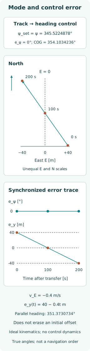
At transfer, set E = +40 m, U = 4.0 m/s, current 0.6 m/s east and actual heading ψ = 345.5224878° true. This heading is −asin(0.25) relative to north. Ideal heading hold retains it unchanged for 200 s, so e_ψ = 0 throughout. These invented values are chosen to illustrate error definitions, not to recommend an intercept maneuver.
Ground velocity is v_E = 4 sin ψ + 0.6 = −0.4 m/s and v_N = 4 cos ψ = 3.8729833 m/s. Its course is atan2(v_E, v_N), wrapped to 354.1034236° true. Thus e_y(t) = 40 − 0.4t m gives +40 m at 0 s, zero at 100 s and −40 m at 200 s, while the heading error remains exactly zero.
Distinguish parallel motion from path capture
A different heading, ψ = 351.3730734°, satisfies 4 sin ψ + 0.6 = 0 under the same speed and current. Holding it removes the cross-track velocity in this toy setting. Starting with an offset, however, would preserve that offset: e_y becomes constant rather than converging to zero. Parallel ground motion and occupation of the desired line are different conditions.
This contrast separates velocity correction from position correction. An actual path-capture function must account for the vessel’s current position, maneuverability and intended path geometry. The example supplies none of its required dynamic behavior. The calculated headings are counterexample inputs, and the 100 s crossing time is a consequence of those inputs, not an available reaction period or navigational allowance.
Keep sensor validity attached to the values
Heading, position and speed have different source chains. A plausible heading signal cannot validate the position used for cross-track calculation. Similarly, two apparently agreeing values may share the same underlying sensor or processing path. A mode review needs source identity, validity and timestamps, not merely the numerical values copied from a display.
For the synthetic trace, all signals are exact and synchronized by assumption. With biased heading, delayed position or changing current, observed error traces would depart from the straight lines shown. That departure would not identify a cause by itself. It would first require checking whether the compared values represent the same epoch, reference point, angle convention and active route leg.
Read alerts in their actual mode
A heading-deviation alert and a cross-track alert refer to different monitored quantities. Their presence, thresholds, delay and presentation must be established from the applicable system documentation and configuration. This article supplies no universal alert setting. In particular, zero heading error in the example does not imply that every relevant monitor would remain silent.
The useful review question is which variable a given alert observes and what assumptions make that variable meaningful. A stale route selection can invalidate the interpretation of an offset even when the displayed distance is computed correctly. An active-mode indication provides context for the control objective; it does not independently certify sensor health, route safety or the adequacy of the chosen preset.
Separate public standards from vessel implementation
The IEC public catalogue identifies IEC 62065:2025 as Edition 3.0, published 16 October 2025 and replacing the 2014 edition. Its abstract relates the standard to the IMO track-control performance standard and reports changes including bridge alert management. Only that public catalogue and abstract were inspected; no paid clause or test procedure is cited here.
The detailed transfer statement above comes from the directly accessible 1998 IMO resolution, not an imagined reading of the full IEC edition. A vessel’s actual approval basis, installed software and operating instructions remain separate evidence. A publication’s newer date alone cannot establish that a particular installation implements every feature in it, nor that a generic illustration matches the equipment’s interface.
Define a reviewable mode-transition record
A useful event record connects the timestamp, requested change, resulting active mode, previous and new preset, actual heading, ground course, active track and signed offset. It also retains source status and units. Those fields make it possible to distinguish a correctly held heading from continued route following without diagnosing a fault merely because the two outcomes differ.
In the original record, the event is idealized track-to-heading transfer, the retained heading is fixed, and the offset changes sign with a constant westward component. No controller failure has been simulated. The case teaches a precise question: which error is presently controlled, and which other quantities must still be interpreted? The answer comes from the objective and evidence, not from the word “automatic” alone.
Sources
- IMO Resolution MSC.74(69), Annex 2, Recommendation on Performance Standards for Track Control Systems. Adopted 12 May 1998; Annex 2 — 1; 4; 5.1.2–5.1.4; 5.1.12–5.1.16; 5.3.5–5.3.7; 6.2.1; 8
- IEC 62065:2025 official publication catalogue. Edition 3.0, published 16 October 2025; replaces 2014 edition — Abstract, publication detail and listed changes