Knowledge / Machinery and energy
Dual-fuel methane slip: flame quenching, crevice volumes and measurement basis
Follow unburned methane from chamber walls and crevices to the exhaust, then distinguish methane-only fractions, fuel-mass percentages and work-specific emissions.
On this page
Methane slip is methane that leaves an engine without being oxidized. It is different from boil-off generated in an LNG tank and from leakage in fuel-handling equipment, although all can contribute to a vessel’s methane inventory. Understanding engine slip requires both a combustion explanation and an accounting boundary. A low-looking percentage and a high g/kWh result can describe the same engine condition when their denominators differ.
Why a functioning flame leaves some methane behind
In a premixed gas charge, the main flame does not necessarily oxidize every small volume. Close to a relatively cool wall, heat loss can become too large for flame propagation to continue. Mixture in that near-wall region may escape the main burn. Very lean bulk regions or incomplete firing can create additional unburned methane. These mechanisms must not all be labelled a full-cylinder misfire.
The IEA AMF research programme distinguishes wall quenching, crevice effects, bulk quenching and post-oxidation. The relative importance depends on engine concept, geometry and operating point. A high-pressure direct-injection gas engine does not expose all its fuel to the same premixed-charge history as a low-pressure dual-fuel engine; one slip factor should not be transferred between them without evidence.
Crevice storage and final exhaust emission are not identical
Narrow regions around a piston’s top land, ring pack and other chamber features can receive unburned mixture during compression while being too narrow for the flame to enter. As cylinder pressure falls, some of that material returns to the chamber. Whether it then oxidizes depends on local temperature, mixing and the time available before discharge. The mass that entered a crevice is therefore not automatically the mass measured at the exhaust.
Wärtsilä lists low-crevice hardware and combustion-control changes as separate methane-reduction measures. This supports the physical distinction between reducing trapped volume and improving the subsequent burn. It does not authorize changing ring clearances or valve timing outside the maker’s approved design. Combustion geometry also serves sealing, lubrication, thermal and mechanical functions.
Keep the engine and vessel boundaries explicit
Define whether the result covers engine-out exhaust, exhaust after an abatement device, crankcase emissions where relevant, or all vessel methane sources. Venting, bunkering losses and tank leakage belong to a wider inventory and should not be silently added to an exhaust-only factor. Conversely, an exhaust measurement cannot establish that the rest of the vessel has no methane emissions.
The FUMES research used onboard and remote plume measurements. Those approaches observe different combinations of sources and operating conditions. A research result needs its engine identification, load information, sampling boundary and uncertainty before it can support a comparison. A fleet mean is not a guaranteed value for one installed engine or a substitute for an approved measurement.
Three denominators answer three different questions
A methane-only unburned fraction divides emitted methane mass by methane entering in the gas fuel. A gas-fuel-mass percentage divides emitted methane by the total methane-containing fuel mass, including its other constituents. Specific emission in g/kWh divides emitted methane by produced work. State whether that work is engine brake work or generator electrical output; electrical conversion losses make those bases different.
IMO’s 2026 guidelines define their Cslip basis using methane-containing fuel excluding pilot fuel and apply a reference-composition correction. That formal quantity must not be confused with an informally quoted methane-only fraction. The calculations below deliberately show the distinction. They are unmeasured teaching cases, not regulatory default factors.
Worked example: one flow, several valid ratios
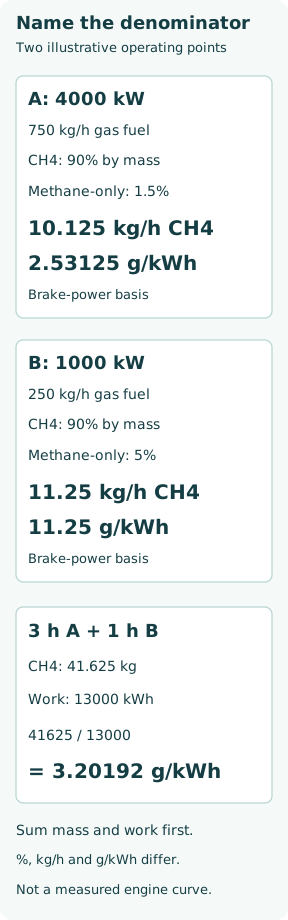
Suppose an engine produces 4,000 kW brake power and consumes 750 kg/h of gas fuel containing 90% methane by mass. For this example only, assume 1.5% of the incoming methane leaves unburned. Methane input is 750 × 0.90 = 675 kg/h, and output is 675 × 0.015 = 10.125 kg/h.
The methane-only fraction is 1.5%, but the raw total-gas-fuel percentage is 100 × 10.125/750 = 1.35%. Work-specific emission is 10.125 × 1,000/4,000 = 2.53125 g/kWh. If the phrase “1.5% slip” had instead meant 1.5% of total gas-fuel mass, the emission would be 11.25 kg/h. A missing denominator changes the physical answer.
To illustrate the reference correction in the cited 2026 guideline, multiplying the raw 1.35% by 0.846/0.90 gives 1.269%. The methane reference mass fraction 0.846 belongs to that specific reporting method. This corrected number is not a new measurement and does not mean that less methane physically left the example engine. Complete reporting also requires the applicable test, scope and verification provisions.
Low output can make g/kWh rise sharply
In a separate low-load case, let brake power be 1,000 kW, gas-fuel flow 250 kg/h, methane mass fraction 0.90 and methane-only unburned fraction 5%. Methane emission is 250 × 0.90 × 0.05 = 11.25 kg/h, giving 11.25 g/kWh. Absolute methane flow is only moderately above the first case, but emissions per unit work are much larger. Both the unburned fraction and the smaller work denominator contribute.
These two points do not define a real load curve. In an actual engine, combustion stability, wall conditions and control mode change with load. Evaluating only a favourable high-load point can miss an important part of the operating profile, but replacing every engine with the same assumed low-load penalty is equally unjustified.
Average the emitted mass and work before dividing
If the teaching engine spends 3 h in the first condition and 1 h in the second, total emitted methane is 3 × 10.125 + 11.25 = 41.625 kg. Work is 3 × 4,000 + 1 × 1,000 = 13,000 kWh. The period-specific result is 41,625/13,000 = 3.20192 g/kWh.
A time-weighted mean of the two instantaneous g/kWh values would instead give (3 × 2.53125 + 11.25)/4 = 4.71094 g/kWh. That is not the period mass/work ratio because output power differs. An approved test-cycle weighting is another defined method and must be applied as specified; it should not be mixed with voyage time weighting or an arithmetic average of percentage factors.
Concentration requires flow and a consistent gas basis
A ppm reading is a concentration, not a mass emission rate. In a simplified molar calculation, methane mass flow is its mole fraction times total exhaust molar flow times methane molar mass. Concentration and flow must both refer to the same wet or dry basis. Removing water raises the numerical concentration even if methane mass flow is unchanged.
For example,1,000 ppm on a wet basis with 10% water vapour by mole corresponds to 1,000/(1−0.10) = 1,111.11 ppm dry. This elementary conversion assumes only water is removed; it does not model sample losses, analyser interference or an official reporting correction. Total hydrocarbons are also not automatically a methane measurement. Species response, calibration gas, methane separation and exhaust-flow determination belong to the measurement method.
A mitigation claim needs comparable before-and-after evidence
Compare the same engine configuration, gas composition, load/power basis, sampling location and measurement method. Include uncertainty, low-load behaviour and any additional fuel or auxiliary energy. A methane oxidation device needs the appropriate exhaust conditions and maintained performance; the mere presence of a catalyst does not establish a constant removal percentage.
For current formal reporting, consult the applicable 2026 framework: MEPC.414(84) superseded the 2025 measurement guideline. The resolution invites voluntary application; its protocol does not itself amend the mandatory provisions of the NOx Technical Code. This article explains the physical and arithmetic basis, not certification of a particular installation. A useful result states where methane was measured, how concentration became mass, what divided that mass, and whether composition correction or cycle weighting changed the reported number.