Knowledge / Machinery and energy
Electric-propulsion regeneration: DC-link energy and braking limits
Track energy returning from a propulsion motor, calculate DC-link voltage rise, and distinguish capacitor headroom, regenerative transfer and resistor braking.
On this page
An electric propulsion machine can return electrical power while opposing shaft rotation. That power does not disappear when the commanded speed is reduced. It must be consumed elsewhere, stored, returned through an available conversion path or dissipated as heat. If incoming energy exceeds those outlets, the DC-link voltage rises. The braking limit is therefore a system energy question as well as a motor-torque question.
A slowing shaft is not automatically regenerating
Define positive shaft speed in the current rotation direction and positive machine torque as torque driving the shaft. Mechanical output power is Pshaft = Tω. When machine torque opposes positive speed, Pshaft is negative: mechanical power enters the electrical machine. Some becomes loss and, in a suitable drive, the remainder can reach the DC link. By contrast, a shaft slowing under water resistance with little machine torque may dissipate most energy hydrodynamically.
A propeller can also be driven by the surrounding flow while the vessel continues moving. The returned energy can then involve the vessel–water interaction, not only the rotational inertia of the motor and shaft. A rotor-only stopping calculation cannot predict an entire crash-stop manoeuvre. The actual torque–speed history and the propulsion system’s permitted quadrants are required.
Draw every possible destination for the returned power
For a simplified link receiving regenerated power, write dEcap/dt = Pregen − Ploads − Pstorage − Preturn − Presistor. Each term is measured at the same DC boundary. Storage and return are positive when they remove power from the link; conversion losses must be included consistently rather than counted twice. A connected device is not necessarily an available energy sink at the moment of braking.
ABB’s braking guide distinguishes a diode supply, which cannot return energy to the AC network, from regenerative supply arrangements and resistor braking. An active front end permits an electrical return path, but the receiving AC system still needs sufficient demand or another approved sink. On a ship, generator sets are not an unlimited destination for reverse power. The switchboard configuration and power-management limits must be included.
Capacitance provides a brief buffer, not a sustained destination
For an ideal capacitor bank, Ecap = ½CV², with capacitance C in farads, voltage V in volts and energy in joules. Between two permitted analysis voltages, available energy headroom is ΔE = ½C(V2² − V1²). Total stored energy and remaining headroom are different quantities. Using ½CV2² as the amount available for a braking event would wrongly count the energy already stored at V1.
For constant net surplus P, V(t) = √(V1² + 2Pt/C). The squared voltage rises linearly; voltage itself follows the square root. Real links have capacitance tolerance, ripple, losses and protective thresholds. A calculation using selected voltages is useful for understanding response time, but those values must never be substituted for the drive’s approved limits.
Worked example: 120 kW fills the headroom in milliseconds
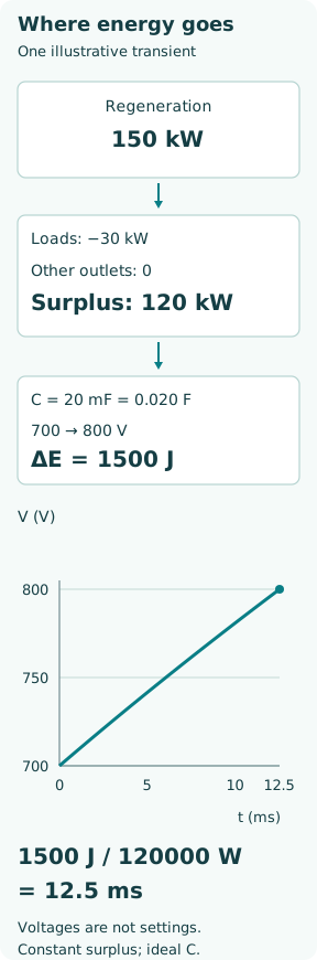
Assume an invented C = 20 mF = 0.020 F link initially at 700 V. Use 800 V as the upper boundary for this calculation only. Suppose 150 kW arrives from regeneration and 30 kW is simultaneously consumed by other link loads. No storage, return or resistor path is active. Surplus power is 120 kW = 120,000 J/s.
The available headroom is ½ × 0.020 × (800² − 700²) = 1,500 J. Time to the upper boundary is 1,500/120,000 = 0.0125 s = 12.5 ms. This is the time predicted by the ideal energy balance, not an observed trip time. It explains why a slow supervisory command cannot be assumed to protect a fast DC-link transient by itself.
Increasing capacitance would increase headroom in direct proportion for the same voltage range, but it would not create continuous braking capacity. It also changes stored fault energy, precharge requirements and the engineered electrical design. Adding capacitance or changing an overvoltage setting is not a remedy that can be inferred from this teaching example.
Separate event energy from peak braking power
In a separate illustrative rotor-only case, let the inertia referred to one shaft be J = 120 kg·m² and speed fall from 1,200 to 600 rpm. Convert with ω = 2πn/60: the speeds are 125.66 and 62.83 rad/s. The kinetic-energy decrease is ½J(ω1² − ω2²) = 710.61 kJ. If 90% reaches the DC link, the returned electrical energy is 639.55 kJ.
If that event lasts 10 s, average returned power is 63.96 kW. It does not specify the peak power or torque. A linear speed ramp with constant opposing inertial torque has a changing instantaneous power because speed changes. The 120 kW surplus in the earlier example is a different, separately assumed transient; it must not be presented as the average of this rotor case.
This rotor calculation neglects propeller hydrodynamic work, shaft friction, changing losses and vessel translation. It is suitable for exposing the distinction between joules and watts. A complete marine braking design needs the actual mechanical duty and all simultaneous consumers or sources.
A braking resistor has current, power and thermal limits
An ideal chopper connects a resistor across the link for part of each switching period. While connected, Presistor,on = V²/R and Iresistor,on = V/R. At approximately constant voltage, switching duty d gives average power dV²/R. This switching duty is distinct from the slower operational braking cycle that determines heating and cooling between manoeuvres.
For a separate hypothetical 6 Ω resistor at 800 V, on-state power is 106.67 kW and current is 133.33 A. At d = 0.75, average dissipation is 80 kW; maintaining that average for 5 s releases 400 kJ as heat. These figures are an electrical calculation, not a selected resistor rating. The 6 Ω value must not be transferred to a real drive: minimum resistance, maximum current and approved component combinations are equipment-specific.
Siemens’ S110 resistor load diagram distinguishes peak power, pulse duration and repetition period. A resistor may tolerate a short high-power pulse yet overheat under repeated events. Conversely, a resistor with adequate accumulated-energy capacity may still exceed the chopper’s instantaneous current limit. Both the short-time electrical limit and the complete thermal duty must pass.
Storage and shared loads help only when they can accept power
A battery’s charge acceptance depends on state of charge, temperature, cell limits and its converter. A high-energy battery near its charge limit may offer little instantaneous braking headroom. A common DC link can use one machine’s regenerative energy in another motoring machine, but the coincidence of these loads must be demonstrated for the manoeuvre being credited.
ABB’s marine DC architecture describes coordinated integration of generators, storage and consumers. That integration supports energy routing; it does not guarantee that every sink remains available after a fault. Review a disconnected battery, loss of a cooling circuit, reduced consumer demand and a bus-section change as distinct configurations. The receiving path needs both electrical continuity and current/energy acceptance.
What happens when the sinks saturate?
Depending on the installed controls, the drive may reduce regenerative torque, lengthen the speed ramp or trip to protect the DC link. These outcomes have different consequences for shaft motion and ship manoeuvring. An overvoltage protective action can preserve electronics without satisfying the originally requested deceleration. The protective design and manoeuvring performance must therefore be assessed together.
Useful evidence records shaft speed and torque, DC voltage, regenerative power, consumer power, battery acceptance limits, chopper duty and resistor temperature on a sufficiently aligned time base. State whether power is instantaneous or averaged. Tests and work on these circuits require the approved isolation procedure: a stopped motor does not establish that the DC link is discharged, and braking resistors may remain hot.
The central check is an energy balance over time. How many joules must leave the mechanical system, how quickly do they arrive electrically, which paths accept them, and what happens if one path disappears? Answering those four questions prevents a capacitor, a large motor rating or a connected battery from being mistaken for unlimited braking capability.